
Specifications


MDS 05-3438A01, Rev. E MDS 4790/9790 Series I/O Guide 69
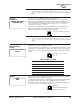
Unit Address The radio’s unit address identifies itself as a unique radio within a network
managed by MDS’ InSite™ NMS software or similar program. This address is
independent of the Multi-Drop Address (above) and is needed only for local and
over-the-air diagnostics and control services of this unit through an NMS program
such as InSite.
The default unit address is the last four digits of the radio’s serial number.
User-programmable unit addresses can range 10000...65000. (Addresses in the
0...9999 range are reserved for use by the factory.) Once the default unit address
is changed, it cannot be reprogrammed.
NOTE: The Unit Address operates independently from the Multi-Drop Address.
(See “Multiple-Drop Address” above for details).
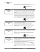
Standby
Equipment
This screen is used to notify the monitoring processor of the presence of a second
radio assembly within the chassis so that it can switch to the alternate unit in the
event of a failure of the primary radio assembly.
To identify the available hardware, press ENTER, then use the up/down arrow
buttons to select:
“defined”, if the chassis is equipped with two radio assemblies
“not defined”, if the chassis equipped with only one radio assembly
The unit does not know if there are one or two radio transceiver assemblies
installed. Make sure you know what hardware is installed before making a change.
Battery Backup The Battery Backup screen is used to set or display the monitoring of the internal
back-up battery voltage (condition) and if an alarm is desired to be sent when the
radio is operating from the internal back-up battery or the voltage falls below
13 Vdc.
Battery Backup “not defined” means the battery is not installed or your do not
desire to monitor its condition. “defined” indicates monitoring is enabled and an
alarm message will be created when the battery voltage is less than 13 Vdc.
To set the radio to monitor the internal back-up battery, press ENTER, then use the
up/down arrow buttons to select “defined”. Press ENTER again to make the
change. To set the radio to ignore the battery condition, press ENTER, then use the
up/down arrow buttons to select “not defined”. Press ENTER again to make the
change.
Key On Data This screen is used to set or display the radio’s keying mode (key-on-data, or
key-on-RTS). In key-on-data mode, the radio will automatically key itself whenever
input data arrives on the DB-25 port. In key-on-RTS mode, the radio will only key
in response to an RTS or PTT signal.
To set the radio to key-on-data mode, press ENTER, then use the up/down arrow
buttons to select ENABLE. Press ENTER again to make the change. To set the
radio to key-on-RTS mode, press ENTER, then use the up/down arrow buttons to
select DISABLE. Press ENTER again to make the change.
UU
UU
nn
nn
ii
ii
tt
tt
AA
AA
dd
dd
dd
dd
rr
rr
ee
ee
ss
ss
ss
ss
22
22
00
00
66
66
77
77
UNIT [10000–65000]
command, Page 55
SS
SS
tt
tt
aa
aa
nn
nn
dd
dd
bb
bb
yy
yy
EE
EE
qq
qq
uu
uu
ii
ii
pp
pp
mm
mm
ee
ee
nn
nn
tt
tt
nn
nn
oo
oo
tt
tt
dd
dd
ee
ee
ff
ff
ii
ii
nn
nn
ee
ee
dd
dd
STANDBY [ON/OFF]
command, Page 52
BB
BB
aa
aa
tt
tt
tt
tt
ee
ee
rr
rr
yy
yy
BB
BB
aa
aa
cc
cc
kk
kk
uu
uu
pp
pp
nn
nn
oo
oo
tt
tt
dd
dd
ee
ee
ff
ff
ii
ii
nn
nn
ee
ee
dd
dd
BATT(ery) [ON/OFF]
command, Page 55
KK
KK
ee
ee
yy
yy
OO
OO
nn
nn
DD
DD
aa
aa
tt
tt
aa
aa
ee
ee
nn
nn
aa
aa
bb
bb
ll
ll
ee
ee
dd
dd