
Specifications


84 MDS 4790/9790 Series I/O Guide MDS 05-3438A01, Rev. E
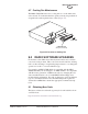
4. Locate the battery cable and connect it to the proper terminals on the
battery. The red wire connects to the positive (+) terminal; the black
wire connects to the negative (–) terminal.
Figure 39. Backup Battery Installation
5. Reinstall the top cover of the radio and set the BATTERY BACKUP
switch to
ON. If the battery is charged, the radio should begin oper-
ating immediately. If it is not charged, the radio must be operated
from an AC power for at least 6 hours before battery backup will be
available.
6. This completes the installation of the backup battery. To remove the
battery from the radio, these steps may be reversed.
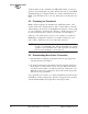
8.3 Front Panel
The front panel is secured to the chassis with spring-loaded latches. To
remove the panel, simply pull out at the bottom edge until it is free from
the chassis (Figure 40). You will also need to disconnect the modular
cable from the back of the panel. Reverse these steps to re-install the
front panel on the chassis.
(P/N 28-1575Axx)
Backup Battery