
User`s guide


144 MDS iNET 900 Series User’s Guide MDS 05-2806A01, Rev. E.1
6.1.2 COM1 Port
To connect a PC to the transceiver’s COM1 port use a DB-9M to DB-9F
“straight-through” cable. These cables are available commercially, or
may be constructed using the pinout information in Figure 6-2 and
Table 6-2.
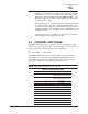
Figure 6-2. COM1 Port (DCE)
(Viewed from the outside of the unit.
)
6.1.3 COM2 Port
To connect a PC to the transceiver’s COM2 port use a DB-9F to DB-9M
“straight-through” cable. These cables are available commercially, or
may be constructed using the pinout information in Figure 6-2 and
Table 6-2.
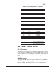
Figure 6-3. COM2 Port (DTE)
Viewed from the outside of the radio
Table 6-2. COM1 Port Pinout, DB-9F/RS-232 Interface
Pin Functions DCE
1 Unused
2 Receive Data (RXD) <—[ Out
3 Transmit Data (TXD) —>[ In
4 Unused
5 Signal Ground (GND)
6–9 Unused
Table 6-3. COM2 Port, DB-9M/EIA-232 Interface
Pin Functions DTE
1 Data Carrier Detect (DCD) In ]<—
2 Receive Data (RXD) In ]<—
3 Transmit Data (TXD) Out ]—>
4 Data Terminal Ready (DTR) Out ]—>
5 Signal Ground (GND)
1
5
9
6
5
1
6
9