
User`s guide


MDS 05-2806A01, Rev. E.1 MDS iNET 900 Series User’s Guide 145
6.2 FUSE REPLACEMENT
PROCEDURE
An internal fuse protects the transceiver from over-current conditions or
an internal component failure. It should not be replaced until you are
certain you are in a safe (non-flammable) environment.
1. Disconnect the primary power source and all other connections to
the unit.
2. Place the radio on its back and remove the four Phillips screws on
the bottom cover.
3. Carefully separate the top and bottom covers. There is a flat ribbon
cable between the top cover’s LEDs and the unit motherboard. You
do not need to disconnect the ribbon cable.
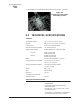
4. Locate the fuse and fuse holder between the
COM1 port and the
power connector. See Figure 6-4 for details.
5. Loosen the fuse from the holder using a very small screwdriver. Use
a small pair of needle-nose pliers to pull the fuse straight up and
remove it.
6. Using an Ohmmeter, or other continuity tester, verify the fuse is
blown.
7. Install a new fuse by reversing the process.
Littelfuse P/N: 0454002; 452 Series, 2 Amp SMF Slo-Blo
MDS P/N: 29-1784A03
6 Data Set Ready (DSR) In ]<—
7 Request-to-Send (RTS) Out ]—>
8 Clear-to-Send (CTS) In ]<—
9 Unused
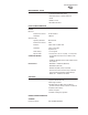
Table 6-3. COM2 Port, DB-9M/EIA-232 Interface
Pin Functions DTE