
Operation Manual


ADV-105 | ENGLISH
6
ADV 105 indoor unit for the
VISTADOOR AUDIO INTERCOM SYSTEM
Thank you for purchasing the VISTADOOR audio indoor unit. You have
bought a high-quality device with speakerphone and handset.
PACKAGING CONTENTS
1 x indoor unit with handset
1 x installation fixtures
1 x operating and installation instructions
1 x drill template
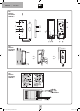
Key
1) Indoor unit
2) Handset
4) Sleep button
6) Power LED
7) Speak button
8) Door release button
13) Alarm button
14) Chime button
15) Intercom volume control
16) Cable entry
17) Connection terminal
18) Handset jack
19) Terminal board slot
20) Handset jack socket
21) Doorbell volume control
22) Connection for VTX-BELL
INSTALLATION
1. Find a suitable location to mount the indoor unit(s) and run the
cables to this point.
2. Lift up the front cover of the indoor unit. You will find retaining
clips on the sides of the indoor unit. Carefully remove the front
cover. Be careful not to damage the cables from the handset jack
and the cable connecting the terminal board to the mainboard.
The cables are connected to the mainboard with connectors. The
connectors can be removed to make assembly easier.
3. There is a hole at the base of the housing (16) in the middle bet-
ween the connection terminals to feed the cables into the housing.
4. Drill four holes (6 mm diameter) into the wall using the drill
template. To do this, use a spirit level to position the drill template
exactly on the wall where you want to mount the indoor unit.
Secure the template with tape and drill the four holes.
5. Remove the template and insert a dowel provided into each hole.
6. Run the connecting cable through the hole in the base of the
indoor unit housing and screw the housing on the wall with the
four screws.
7. Now, you can easily cut the cables to the correct length and
connect them to the appropriate connection terminals.
8. Then, insert the terminal board connector and the handset jack in
the appropriate slots on the mainboard (the white connector of
the terminal board in the white slot and the black connector of the
handset jack in the black slot).
9. The front cover can now be put on again. To do this, hold the front
cover to the housing base on the right-hand side and press it gently
on the base of the housing. See also figure 2. Ensure that the but-
tons do not get jammed and the retaining clips clip firmly in place.
10. Connect the handset to the spiral cable. The connectors on the
spiral cable fit in the handset jack only one way.
11. Connect the other side of the spiral cable to the indoor unit. The
spiral cable connector fits only one way in the handset jack on the
indoor unit.
12. Set down the handset.
OPERATING THE DEVICE
Connecting to the power supply
The power supply can be connected to either the internal and/or
external station. Each station has screw terminals for this purpose.
It is also possible to connect the electricity supply directly to the signal
line, e.g. if all the signal lines were run from the fuse box to the exter-
nal and indoor units. The power supply unit must then be connected in
parallel with earth (ground) and +15 volts.
One power supply unit can supply power to up to eight stations. A se-
cond power supply unit is needed if there are more than eight stations.
NOTE: Do not connect the power supply unit to the mains unit until
the system has been completely installed. Otherwise, the system could
short circuit during installation, which could, at worst, destroy
the device.
STEP ONE
1. Connect the power supply unit to the mains.
2. Press a doorbell on the external station.
3. Wait until the indoor unit(s) return(s) to standby.
If multiple external stations are connected in parallel, repeat steps 2
and 3 for each external station.
The system is now operational.
SYSTEM FUNCTIONS
Doorbell
If somebody presses the doorbell on the external station, your doorbell
chime will ring on the indoor unit, and the speak and door-release
buttons will flash for approx. 60 seconds.
Voice communication
Either pick up the handset and talk to the visitor or press the speak
button once.
The light around the speak button stays blue while voice communica-
tion is established.
To end voice communication, either put the phone down or press the
speak key. You can establish voice communication at any time; the
doorbell does not have to ring beforehand, just simply lift the handset.
Door release
A connected door release mechanism is activated for approx. six seconds
or one second by pressing the door release button (see instructions
for the external station used); you do not need to hold down the door
release button. A double beep on the external and indoor unit confirms
the door has been released and the green name plate also lights up
green if the door release mechanism is activated.
ADV-105_I-Manual_Fin3+3mm.indd 6 30.08.12 16:54