® DS P/N 14-0500-00 06/00
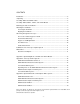
CONTENTS Introduction ........................................................................................................................5 Unpacking ..........................................................................................................................5 Assembly: 60mm and 70mm models ................................................................................5 Assembly: 80mm, 90mm, 114mm, and 127mm Models ....................................................
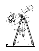
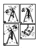
3 2 1 19 4 5 6 11 9 14 7 18 12 10 16 17 15 20 8 21 13 13 13 A -4-
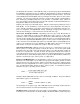
Assembly and Operating Instructions for Meade® Digital Electronic Telescope Series 60mm (2.4"), 70mm (2.8"), 80mm (3.1"), 90mm (3.5") Refracting Telescopes; 114mm (4.5"), and 127mm (5") Reflecting Telescopes Numbered references are to the figures on the pages of this manual. Example: “D-4” refers to item 4 of Fig. D. WARNING! Never use a Meade® DS Telescope to look at the Sun! Looking at or near the Sun will cause instant and irreversible damage to your eye.
1 5 7 4 6 6 5 7 2 8 3 2 1 9 3 B 9 4 9 D 6 1 5 11 4 8 9 7 4 2 2 5 3 3 1 5 E 10 10 10 C -6-
use a “+” (Phillips-head) screwdriver to tighten the bolt to a “firm feel.” Do not overtighten. Note that each tripod leg includes a flip-lock (A-13) for adjusting the overall length of the tripod. These flip-locks should all face inward as the legs are attached to the yoke mount. With the tripod legs attached to the yoke mount and sitting on a flat surface, spread the legs out gently until all legs are fully spread out.
3 2 6 x 30mm 176mm (6.9") 30mm (1.2") 2 3 148mm (5.8") 24mm (0.
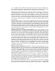
screwdriver, secure the bracket in position by tightening the two attachment screws (G-1) inside the bracket (these screws are placed inside the bracket at the factory) into the mating threads (G-6) located on the focuser housing, or (in the cases of 114mm and 127mm models) located on the mounting block (C-7). Slide the viewfinder (G-2), eyepiece-end (G-8) first, into the viewfinder bracket. (Remove the rubber eyecup (G-8) from the viewfinder before sliding the viewfinder into the bracket.
The diagonal mirror permits a comfortable 90° angle for observing sky objects with DS 60mm through 90mm refracting telescopes; in addition the diagonal mirror results in an upright, but reversed left-for-right, image through the telescope during terrestrial observations. Loosen the vertical (A-14) and horizontal (A-15) locks, by turning the lock knobs about one turn counterclockwise. The telescope’s main tube now moves easily in either vertical or horizontal directions.
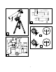
obtained when an eyepiece is used alone. In the example above a 25mm eyepiece results in 28X magnification with the Meade 60mm DS telescope; when this same eyepiece is used in conjunction with a 2x Barlow lens, power is doubled to 56X. To use the Barlow, insert it into the telescope’s focuser/eyepiece-holder (A-17), followed by the diagonal mirror and an eyepiece. (With Meade 114mm and 127mm DS telescopes, insert the Barlow into the telescope’s focuser/eyepiece-holder, followed directly by an eyepiece.
2 1 2 3 M 1 3 2 Q 1 2 N 1 2 2 3 R 3 4 1 5 P 2 4 S - 12 - 3
Appendix 1: Optical Alignment of 114mm and 127mm Models Meade DS 60mm, 70mm, 80mm, and 90mm refracting telescopes are optically aligned (collimated) at the factory prior to shipment, and it is never necessary to re-collimate the optics of these models. Meade DS 114mm and 127mm reflecting telescope models are also factoryaligned, but may occasionally require re-alignment, particularly if the telescope has received rough handling in shipment.
2 1 T 1 2 U - 14 -
Appendix 2: Telescope Control Systems Depending on the Meade DS telescope model, one of the following manual or electronic control systems may be included in the telescope’s standard specifications. (Telescope specifications are generally listed on the box in which the telescope is packed.) Alternately, any of these control systems may be purchased separately as an optional feature.
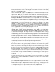
2 6 1 5 3 7 4 V COMPUTER CONTROL HBX AZ ALT 5 AUX 12v W 1 IN FOCUS 2 OUT 3 3 2 4 IN FOCUS OUT SPEED 6 MODE MEADE 1 X Y - 16 - SPEED MODE MEADE
3. Attach the horizontal motor assembly (V-4) to the telescope by following the same procedure outlined in step 2, above. Note: With both the vertical and horizontal motor assemblies attached, the telescope now appears as in Fig. Y. (Note that cords have been omitted from Fig. Y for clarity.) 4. Plug in the following cords to the control panel (V-5 and Fig. W): a. Cord from the vertical motor assembly (V-1) plugs into the ALT (altitude, or vertical) jack (Fig. W). b.
5. The IN and OUT keys are used in conjunction with the optional Meade #1240 Electric Focuser. With the #1240 unit attached to the telescope’s focuser, precise focusing of the telescopic image may be accomplished directly from the Electronic Controller. Detailed instructions are included with the #1240 Electric Focuser. 6. Note that the telescope’s accessory shelf (A-8) includes a holder (A-21) for the Electronic Controller. 7.
Appendix 3: Optional Electronic and Computer Drive Systems Available for Your Meade Digital Electronic Series Telescope Your Meade DS telescope can be equipped with the latest in high-technology electronic drive systems. These systems attach to Meade DS telescopes in minutes and greatly extend the usefulness and excitement of telescope operation.
ADVANCED PRODUCTS DIVISION Meade Instruments Corporation World’s Leading Manufacturer of Astronomical Telescopes for the Serious Amateur 6001 Oak Canyon, Irvine, California 92618 ■ (949) 451-1450 FAX: (949) 451-1460 ■ www.meade.