
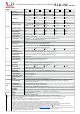
Datasheet


AC/L(Brown)
AC/N(Blue)
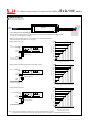
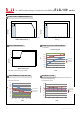
DIMMING OPERATION
ELG-100
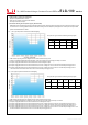
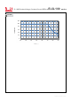
◎ Applying additive 0 ~ 10VDC
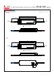
◎ Applying additive 10V PWM signal (frequency range 100Hz ~ 3KHz):
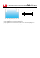
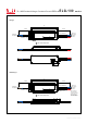
◎ Applying additive resistance:
Note : 1. Min. dimming level is about 8% and the output current is not defined when 0%< out<8%.I
2. The output current could drop down to 0% when dimming input is about 0k or 0Vdc, or 10V PWM signal with 0% duty cycle.Ω
Vo+
Vo-
DIM+
DIM-
+
+
+
-
-
-
“DO NOT connect "DIM- to Vo-"
Additive Voltage
Vo+
Vo-
DIM+
DIM-
+
+
-
-
“DO NOT connect "DIM- to Vo-"
Additive PWM signal
Vo+
Vo-
DIM+
DIM-
+
+
-
-
“DO NOT connect "DIM- to Vo-"
Additive Resistance
0V 1V 2V 3V 4V 5V 6V 7V 8V 9V 10V
10%
0%
20%
30%
40%
50%
60%
70%
80%
90%
100%
Output current (%)
0%
10% 20% 30% 40% 50% 60% 70% 80% 90% 100%
10%
0%
20%
30%
40%
50%
60%
70%
80%
90%
100%
Output current (%)
10%
0%
20%
30%
40%
50%
60%
70%
80%
90%
100%
Output current (%)
Dimming input: Additive voltage
Duty cycle of additive 10V PWM signal dimming input
70~100W Constant Voltage + Constant Current LED Driver
※ 3 in 1 dimming function (for B/AB-Type)
Output constant current level can be adjusted by applying one of the three methodologies between DIM+ and DIM-:
0 ~ 10VDC, or 10V PWM signal or resistance.
Direct connecting to LEDs is suggested. It is not suitable to be used with additional drivers.
Dimming source current from power supply: 100 A (typ.) μ
* DIM+ for B/AB-Type
DA+ for DA-Type
PROG+ for D2-Type
* *DIM- for B/AB-Type
DA- for DA-Type
PROG- for D2-Type
Short
10K/N 20K/N 30K/N 40K/N 50K/N 60K/N 70K/N 80K/N 90K/N 100K/N
(N=driver quantityfor synchronized )dimming operation
Dimming input: Additive resistance
DIM-(White)**
DIM+( )*Blue
Vo+(Red)
Vo-(Black)
ELG-100 series
File Name:ELG-100-SPEC 2018-09-30