GC120 Instruction Manual
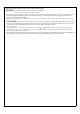
GC120 Instruction Manual POWER LED R7B (standard) 4 3 1 2 R7B : UL2464 18AWGx4C 1200 50mm AD1 : SJTW 18AWGx2C 1200 50mm AD1 (optional) DC output connector (optional) DC output connector (standard) AD1 R7B (KYCON KPP-4S or equivalent) 4 3 1 2 PIN NO.
Status Under General Operation: At the beginning stage of operation, the charger provides the largest current with 13.6Vdc of output voltage (for 12V batteries) to charge batteries. The LED indicator will lighten in red. After a period of time (probably a couple of hours, based on the capacity of batteries), the charging current will decrease gradually. After reaching 10% of its maximum value, the charger will go into "floatingcharge" stage. The LED indicator will turn to green.
IMPORTANT SAFETY INSTRUCTIONS - SAVE THESE INSTRUCTIONS DANGER - TO REDUCE THE RISK OF FIRE OR ELECTRIC SHOCK. CAREFULLY FOLLOW THESE INSTRUCTIONS. 1.This manual contains important safety and operating instructions for battery charger Models GC120A12,GC120A24 and GC120A48. 2. SAVE THESE INSTRUCTIONS - This manual contains important safety and operating Instructions for battery charger Models GC120A12, GC120A24 and GC120A48. 3.