
Datasheet

The remote sensing compensates voltage drop on
the load wiring up to 0.5V.
8
8
7
7
CN100
AUX
AUX
AUX
GND
GND
GND
-S
-S
-S
AUXG
AUXG
AUXG
DC-OK
DC-OK
DC-OK
+S
+S
+S
2
2
1
1
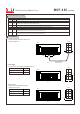
1.Remote Sense
Sense l ines should
be twi sted in pairs
LO AD
-
+
+S -S
(Pin7) (Pin8)
Fig 1. 1
Between DC-OK(pin5) and GND(pin6)
3.3 ~ 5.6V
0 ~ 1V
Output Status
ON
OFF
DC-OK signal is a TTL level signal. High when PSU turns on.
CN100
2.DC-OK Signal
Fig 2. 1
Fig 3. 1
5 DC-OK
DC-OK Signal is a TTL level signal, referenced to pin6(DC-OK GND). High when PSU turns on.
7 +S
Positive sensing. The +S signal should be connected to the positive terminal of the load. The +S and -S leads should be twisted in pair to
minimize noise pick-up effect. The maximum line drop compensation is 0.5V.
8 -S
Negative sensing. The -S signal should be connected to the negative terminal of the load. The -S and +S leads should be twisted in pair to
minimize noise pick-up effect. The maximum line drop compensation is 0.5V.
6 GND
This pin connects to the negative terminal(-V). Return for DC-OK signal output.
RC-
RC-
RC-
RC+
RC+
RC+
CN100
CN100
CN100
8
8
8
7
7
7
2
2
2
1
1
1
450W Single Output Medical Type
File Name:MSP-450 -SPEC 2014-0 2-12
MSP -45 0
s e ries
Function Description of CN100
Pin No. Function
Description
Function Manual
1
2
RC+
RC-
Remote control ground.
Turns the output on and off by electrical or dry contact between pin 2 (RC-), Short: Power OFF, Open: Power ON.
3
4
AUX
AUXG
Auxiliary voltage output, 4.75~5.25V, referenced to pin 4(AUXG). The maximum load current is 0.3A. This output has the built-in oring
diodes and is not controlled by the "remote ON/OFF control".
Auxiliary voltage output ground. The signal return is isolated from the output terminals (+V & -V).
8
7
2
1
Between RC+(pin1) and RC-(pin2)
SW ON (Short)
SW OFF (Open)
Output Status
OFF
ON
The PSU can be turned ON/OFF by using the
"Remote Control" function.
SW
CN100
3.Remote Control