
User manual

2
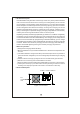
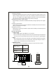
Assemb ly guidelines:
1.The ch arger should be turned OFF prior to battery connection. Suitable wire gauge
2. Af te r pl ugging in th e AC pow er c ab le, flick the ON/ OFF (0/-) switch t o the ON(-)
position. T he LED indicator on the switch will lig ht up.
should be chosen based on rated charging current of the charger unit. Double-check
battery polarity before making the battery connection. Positive terminal of the charger
must be co nnected to + of the b atte ry and ne gative terminal to of the battery. Also,
make sure the posit ive and negative ter minals of the charger are not accidentall y
shorted together.
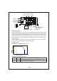
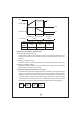
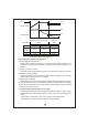
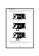
3.Derating c urve
3.1 Charging curren t VS temperature
AMBIENT TEMPERATURE ( )℃
20
40
60
80
100
-20 0 10 20 30 40 50 60 70
(HORI ZONTAL)
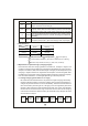
Figure 2.2 Back Panel
LED
Indicator
Function
Connect or
2/3/8 stage
select io n switch
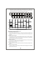
{
+
+
Battery ABattery B
-
-
Stage 8/3/2
Please che ck batter y
polarity before
connection
WARNING :
Battery B
Positive
Battery A
Positive
Common
Negative
Pin No. Function
Description
1,2 RY13
Rela y contact rating (max.): 30V/1A. "Short" when bank A is full.
"Open" when bank A is still charging.
4.Function description for CN100