PB-600 Instruction Manual
PB-600 Instruction Manual Index 0.Product description................................................................................. 1 1.Notes on operation ................................................................................. 1 2.Front and back panel .............................................................................. 1 3.Derating curve ........................................................................................ 2 3.1 Charging current VS temperature.......................
0.Product description PB-600 is MW's next generation smart charger. It has many of the protective features that consumers would like to have in a charger including battery misconnection (wrong voltage), reverse polarity, battery disconnection or not connected, and battery failure analysis. The latest high efficiency switching topology plus microcontroller power management are utilized in its design.
Battery Positive LED Indicator Common Negative Power Stage 8/3/2 2/3/8 stage selection switch Function Connector 10 + WARNING : - Please check battery polarity before connection Battery Figure 2.2 Back Panel Assembly guidelines: 1.The charger should be turned OFF prior to battery connection. Suitable wire gauge should be chosen based on rated charging current of the charger unit. Double-check battery polarity before making the battery connection.
Pin No. Function Description 5,6 RY15 Relay contact rating (max.): 30V/1A. "Short" when the unit is working normally; “Open” when the unit is in a faulty condition 7,8 Temperature sensor which comes with the charger can be connected to the unit to allow temperature compensation of the charging voltage. GND/RTH If the temperature sensor is not used, the charger can still work normally. 9,10 RC-/RC+ Turn the output ON and OFF by electrical or dry contact between pin10 (RC+) and pin9 (RC-).
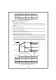
State PB-600-12 PB-600-24 PB-600-48 Constant Current 40A 21A 10.5A V boost 14.4V 28.8V 57.6V Figure 6.1 2 stage charging curve Explanation for 2 stages charging curve (0)Initial stage (battery analysis): Check battery voltage level to see if it is within the normal range, whether or not a battery is connected, or if the battery is already full and further charging is not required. (1)Stage 1 (constant current): A constant current is provided so the battery can be quickly charged to 2.
Explanation for 3 stages charging curve (0)Initial stage (battery analysis): Check battery voltage level to see if it is within the normal range, whether or not a battery is connected, or if the battery is already full and further charging is not required. (1)Stage 1 (constant current): A constant current is provided so the battery can be quickly charged to 2.4V per cell. (2)Stage 2 (constant voltage): A constant voltage of 2.
Explanation for 8 stages charging curve (0)Initial stage (battery analysis): Check battery voltage level to see if it is within the normal range, whether or not a battery is connected, or if the battery is already full and further charging is not required. (1)Stage 1 (pulse charging): Pulse charging is used to revive tired lead acid battery which is either improperly charged/discharged or allowed to self-discharge as occurs during non-use. Basically, help to restore its normal chemical properties.
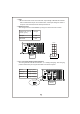
7.2 PFC ◎Built-in active PFC circuit: PF>0.95 when input voltage is between 90~230Vac with full load at the output. On the other hand, if the input voltage is >230V or output is not at full load, the PF will drop below 0.95. 7.3 Remote control The charger can be turned ON/OFF by using the "remote control" function. Between RC+ (pin10) and RC- (pin9) Charger SW open ON SW closed OFF CN100 1 RY13 RY13 2 Power Stage 8/3/2 NC NC RY15 RY15 10 GND RTH 9 + - RC- RC+ 10 Battery SW 7.
7.5 Reverse polarity protection With built-in battery reverse polarity detection circuit. When the battery is connected in reverse at the output terminal of the charger, the output relay circuit will remain open. 7.6 Fan speed control With built-in fan speed control circuit, the fan will automatically change speed depending on load condition. CN100 7.
8.Wiring for battery Select suitable wire guage based on rated charging current. Refer to the following table for minimum wire gauge. We highly recommend using RED wire for + connection and BLACK wire for-connection: CROSS SECTION(mm 2 ) AWG Max. Current(A) UL1015(600V 105℃) 14 2.1 12 12 3.3 22 10 5.3 35 7 10 46 6 16 60 4 25 80 9.Suggested battery capacity Model Battery capacity PB-600-12 135-400AH PB-600-24 70-210AH PB-600-48 35-105AH Note: 1.
2.Batteries in parallel Wh en 2 bat ter ies a re c onnect ed i n pa ral lel, v olta ge r em ai ns th e s am e a nd t he capacity (Ah) doubles. For example, 2 x 12V 100Ah batteries connected in parallel = 12V 200Ah. + - Battery + - Battery 11.
N o . 2 8 , W u q u a n 3 r d R d . , Wu g u D i s t .