
User manual


8
NTC
+
Battery
-
10
Power
Stage 8/3/2
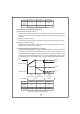
The temperature
sensor can either
be attached to the
battery or placed
in its surrounding
environment.
9
1
10
CN100
RY13
NC
RY15
GND
RC-
RY13
NC
RY15
RTH
RC+
2
RY13
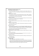
7.8 Output OK relay (RY13)
Battery
Battery full
Color of LED
Charging
Between pin1 and pin2
ON (short) Green
OFF (open) Orange
9 Temperature compensation7.
Temperature sensor which comes with the charger can be connected to the unit
to allow temperature compensation of the charging voltage. If the temperature
sensor is not used, the charger can still work normally.
9
1
10
CN100
RY13
NC
RY15
GND
RC-
RY13
NC
RY15
RTH
RC+
2
RY15
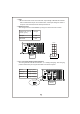
7.5 Reverse polarity protection
7.6 Fan speed control
7.7 Charger OK relay (RY15)
With built-in battery reverse polarity detection circuit. When the battery is connected
in reverse at the output terminal of the charger, the output relay circuit will remain
open.
With built-in fan speed control circuit, the fan will automatically change speed
depending on load condition.
Work normally
Charger
Failure or prote ction
function activated
ON (s hort)
Bet ween pin5 and pin6
OFF (open)