
User manual


2
AMBIENT TEMPERATURE ( )℃
20
40
60
80
100
-20 0 10 20 30 40 50 60 70
(HORIZONTAL)
INPUT VOLTAGE (VAC) 60Hz
90 95 100
90
100
80
70
60
50
40
115 264
+
Battery
-
Power
Stage 8/3/2
10
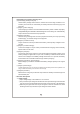
Battery
Positive
Common
Negative
LED
Indicator
Function
Connector
2/3/8 stage
selection switch
Please check battery
polarity before
connection
WARNING :
Figure 2.2 Back Panel
Assembly guidelines:
1.The charger should be turned OFF prior to battery connection. Suitable wire gauge
2. After plugging in the AC power cable, flick the ON/OFF (0/-) switch to the ON(-)
position. The LED indicator on the switch will light up.
should be chosen based on rated charging current of the charger unit. Double-check
battery polarity before making the battery connection. Positive terminal of the charger
must be connected to + of the battery and negative terminal to of the battery. Also,
make sure the positive and negative terminals of the charger are not accidentally
shorted together.
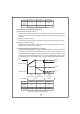
3.Derating curve
3.1 Charging current VS temperature 3.2 Charging current VS input voltage
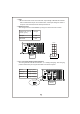
Pin No. Function
Description
1,2 RY13
Relay contact rating (max.): 30V/1A. "Short" when battery is full.
"Open" when battery is still charging.
4.Function description for CN100