
User Instructions


8
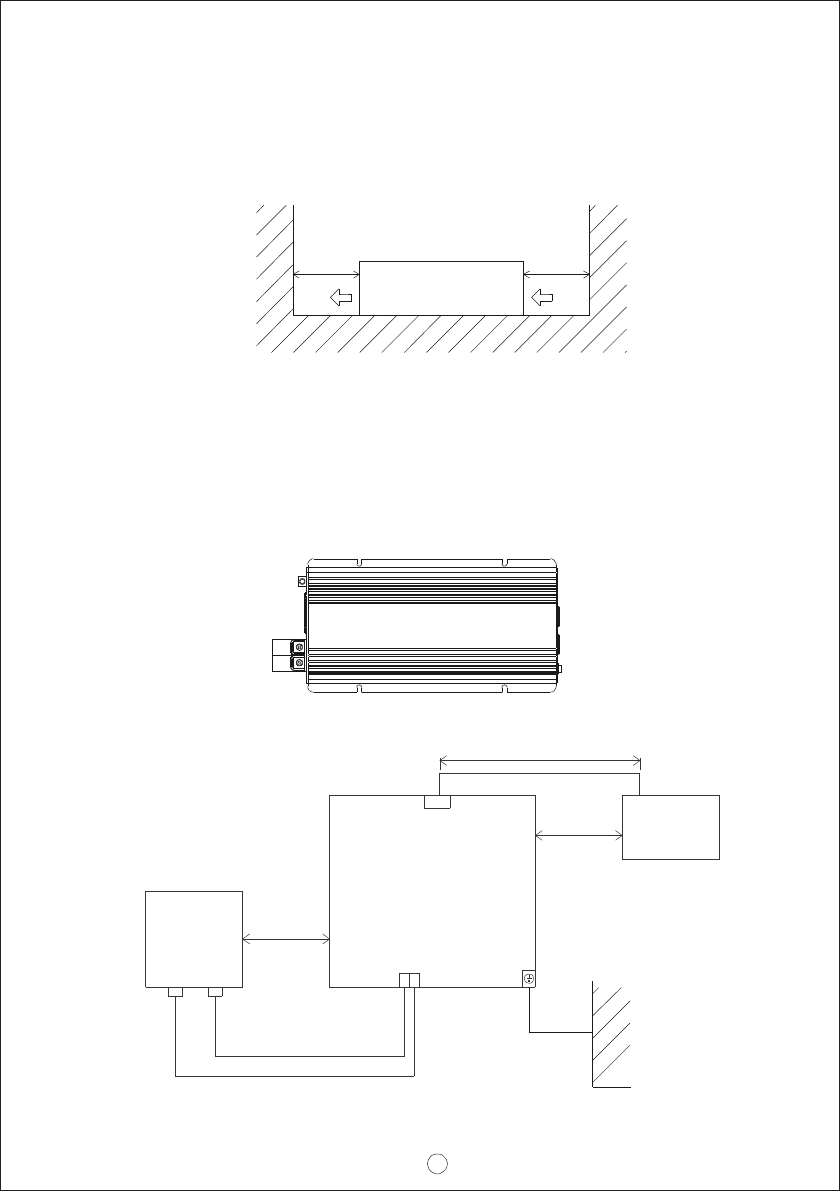
Figu re 6.1: Example of In stallation
>15cm
Inverter
Air
>15cm
Air
TS-700/1000
DC I/P
-
+
Chassis
Wall or system FG
+
-
Battery
Should less th an 1.5m
L arger than
1 5cm
LOAD
As short as possi ble
A C O/P
Larger tha n
15cm
(E)Example of system diagram
(C)Requirement of Install ation:
The un it should be mounted on a flat surface o r holding rack with suitable
strength. In order to e nsur e th e lifespan o f the uni t, please refrain from
operating in environment of high dust or high moisture. This is a power supply
with built-in DC fan. Please make su re that ventilation is not blocked. There
should be no barriers within 15cm of the ventilating holes.
(D)Mounting Suggestion :
There are 4 sem i-circular cutout on the s ide flanges of the inverter. It can be
used for fixing TS-700/1000 onto the system enclosu re.
We high recommend mo unt ing in the ho rizontal position. Please make sure
ventila tion openings are free from obstru ction.