PB-1000 Instruction Manual
PB-1000 Instruction Manual Index 0.Product description................................................................................. 1 1.Notes on operation ................................................................................. 1 2.Front and back panel .............................................................................. 1 3.Derating curve ........................................................................................ 2 3.1 Charging current VS temperature .....................
0.Product description PB-1000 is MW's next generation smart charger. It has many of the protective features th a t co n su mer s wo u ld like to h ave in a cha rg er inclu din g ba tte ry misco nne ctio n (wrong voltage), reverse polarity, battery disconnection or not connected, and battery failure analysis. The latest high efficien cy switc hing topolog y plus microc ontrolle r po wer m an age men t ar e utilize d in its d esig n.
Battery B Battery A Common Positive Positive Negative LED Indi cator { 2/3/8 stag e se lect io n s witc h Func tion Connec t or Stage 8/3/2 + - Battery B + - Battery A Figu re 2.2 Ba ck P anel WARNING : Please check batter y polarity before connection Assemb ly guideline s: 1.The ch arger should be turned OFF prior to battery connection. Suitable wire gauge should be chosen based on rated charging current of the charger unit. Double-check battery polarity before making the battery connection.
Pin No. Function Description 3,4 RY14 Rela y con tact rating (max.): 3 0V/1A. "Short" when bank B is f ull. "Open" when ban k B is still cha rg ing . 5,6 RY15 Re lay conta ct ra ting (max.): 30V/1A. "Short" w hen the unit is work ing prope rly. "Open" when th e u nit has faile d or prot ect io n has a ctiv ated. 7,8 Temperature sensor which comes with the char ger ca n be conne cted to the unit to allow temperature compensation of the charging v oltage.
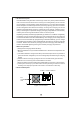
Start V boost Charge Voltage 100% 10% Charge Current stage 1 stage 2 Constant Current Constant Voltage Orange Color of LED Battery Full Green State PB-1000-12 PB-1000-24 PB-1000 -48 Constant Current 60A 34.7A 17.4A V boost 14.4V 28.8V 57.6V Fig ure 6.
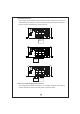
Start V boost V float Charge Voltage 100% 10% Charge Current stage 1 Constant Current stage 2 stage 3 Constant Voltage Battery Full Orange Color of LED Green State PB-1000-12 PB-1000-24 PB-1000 -48 Constant Current 60A 34.7A 17.4A V boost Vfloat 14.4V 13.8V 28.8V 27.6V 57.6V 55.2V F igure 6.
◎A dva ntag e of floa t an d ma intain s tage : Aft er LED t urns gre en, m ainten ance charge is provided so the battery is always in a full state. User will have access to a full battery wh enever it is disconnected from the charger.
(5)Stage 5 (analysis): The cha rger will sto p ch argi ng fo r 2 m inu tes to de term ine battery sta tus. If th e battery voltage is higher than 2.1 V per cell, the battery is d etermined as OK and will move on to stage 6. If the battery voltage is lower than 2.1V per cell, the battery fail indication will co me O N and the charger will stop charg ing. (6)Stage 6 (rec ondition boost charge): Boost voltage is provided to recondition the battery storage capacity to its original state.
7.4 Tw o battery banks The cha rge r ca n be hoo ked up t o tw o ba ttery ba nks (A a nd/o r B) . Co n nec t th e battery bank(s) as below. If you are connecting 2 battery banks at the same time, kee p in mind that it m ust sha re a com mon ground . Stage 8/ 3/2 + - Battery A Stage 8/ 3/2 + - Battery B Stage 8/ 3/2 + - Battery B + - Battery A 7.5 2, 3, or 8 stage charging mode selection Th e ch arge r fe a tur es u ser s ele ctab le 2 , 3, o r 8 s tag e ch argi ng.
Switch C hargin g mod e Slide right 2 sta ge ch arging Mid dle 3 sta ge ch arging Slide left 8 sta ge ch arging Stage 8/3/2 Stage 8/3/2 + - Ba ttery B + - Batte ry A 7.6 Reverse polarity p rotection With built-in battery reverse polarity detection circuit. When the battery is connected in reverse at the output terminal of the charger, the output relay circuit will remain ope n. 7.
7. 10 Temperature compensation Temperature sensor which comes with the charger can be connected to the unit to allow temperature compensation of the charging voltage. If the tem perature sensor is not used, the ch arger can still w ork normally. Stage 8/3/2 The t emperature senso r can either be attached to the batte ry or p laced in its surrou nding envir onmen t. + - Battery B NTC + - Battery A 8.Wiring for battery Select suitable wire gu age based on rated charg ing current.
10.S eries and parallel connection o f batteries 1.Ba tteries in series Vo ltag e ca n be do uble d wh e n 2 ba tteri es a re c onn e cte d in seri es. H ow eve r, th e capacity (Ah) will remain the same. For example, 2 x 12V 100Ah batteries connected in series = 24V 100 Ah. + - + Battery - Battery 2.Ba tteries in parallel Wh en 2 ba tt er ies a re c onn e ct e d i n pa ra ll e l, v o lta g e r e ma in s t h e s a m e an d th e capacity (Ah) d oubles.