TN/TS-1500 Inverter Instruction Manual
TN/TS-1500 Inverter Instruction Manual Index 1. Safety Guidelines ............................................................................... 2. Introduction ........................................................................................ 2.1 Features ........................................................................................ 2.2 Main Specification ........................................................................ 1 1 2 2 2.3 System Block Diagram ............................
1.Safety Guidelines (Please read through this manual before assembling TN/TS-1500) Risk of electrical shock and energy hazard. All failures should be examined by the qualified technician. Please do not remove the case of the inverter by yourself! After connecting the AC input of the inverter to the utility, the AC outlet of the inverter will have AC output even if the power switch on the front panel is in the OFF position. It is highly recommended to mount the unit horizontally.
TN-1500 series will automatically detect the input sources (whether AC main or solar panels exist) and then adjust its internal setting. Users can also set up the operating mode, output voltage, frequency, and saving mode by themselves based on their special needs, geographic area, and environmental conditions. With pure sine wave output, TN/TS-1500 can provide 1500W continuously, 1750W for 3 minutes, or 20~40A of peak current for all kinds of load such as inductive, capacitive, or resistive.
2.3 System Block Diagram TN-1500 Inverter EMI filter AC Input CPU Controller LED Display AC charger Fuse Circuit Breaker Solar charger 200V DC /400V DC Battery 12V/24V/48V Fuse Polarity detect DC/DC Converter DC/AC Inverter 120V/230V 50Hz/60Hz LOAD AC Output Solar Panel Figure 2.1 System Block Diagram 3.User interface 3.1 Front Panel A POWER on/off switch: The inverter will turn OFF if the switch is in the OFF position.
B F AC OUTPUT SOLAR CHARGE ON AC CHARGE A BATTERY OFF Setting LOAD 100 E 100 INVERTER On it Br e 0 er Ci cu AC IN BY PASS Saving se t es Pr s Bat Low ak r 0 C to R e G Remote port D Figure 3.1: Front Panel (TN-1500) 3.2 LED Indicator on Front Panel Battery Capacity Indicator: represents the remaining capacity of external batteries.
3.4 Rear Panel A Battery input (+), (-). B Utility / AC inlet (IEC320). C Solar panel input terminal. D Frame ground (FG). AC INPUT Solar Input (30A max) C NEG B DC INPUT POS Reverse Polarity Will Damage The Unit. Chassis Ground A Cat.No.(1GG1HS-212) Wire Range(10-4 AWG Str Cu Soldered Wires) Torque (17.7-26.5 in lb) D Fig 3.2: Rear Panel (TN-1500) 4.
4.1 Explanation of UPS Mode Control Logic ON ON Utility Power OFF OFF Power-On Re-power-on ON ON By pass mode OFF OFF ON Inverter Mode OFF 28.5V t ON ON OFF OFF t 28.5V 28.5V 28.5V 25.4V 26.5V 26.5V 22.5V (Alarm) 26.5V Battery voltage 21V(Shut-down) t 29.0V Solar charger state AC charger state ON ON ON OFF ON ON t2 OFF OFF OFF t3 t ON OFF t1 ON OFF OFF t4 t5 t6 t7 t8 t9 t10 t t11 t12 Figure 4.
t3: At this time period, TN-1500 is still in the Bypass mode. The battery voltage level will decrease gradually due to standby power dissipation. When the batteries are consumed to around 75% of their capacity (battery voltage around 26.5V) the CPU will restart the charger. The CPU will use charging current of 3A as a guide point. When the provided charging current is under 3A, the AC charger will be turned ON (e.g. Night time or cloudy day).
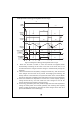
4.2 Explanation of Energy Saving Mode Control Logic ON Utility Power OFF Power-On ON ON Bypass mode OFF OFF ON Inverter mode ON OFF OFF OFF 28.5V 26.5V Battery voltage Solar charger state AC charger state 26.5V 22.5V (Alarm) 22.5V (Alarm) 26.5V 22V ON ON 21.0V (Shut-down) ON OFF t ON ON OFF OFF t1 t ON OFF OFF OFF t 28.5V 28.5V 28.5V t ON t2 t3 t4 t5 t6 t7 t t8 Figure 4.
t5: When the capacity of batteries go down to about 75% (battery voltage around 26.5V), solar charger will restart and begin charging. t6: If the energy provided by the solar panels is lower than consumed by the loads, voltage of battery bank will decrease gradually to 20% of its capacity (battery voltage around 22V), the built-in buzzer will be activated and inform the users to take proper action.
5.3 Procedure of Setting Operating Mode, Output Voltage, Frequency, and Saving Mode Note: TS-1500 does not have Step 3~5. STEP 1: The inverter should be turned off while resetting. Input batteries should be connected, AC main can either be connected or disconnected, and the loads should be removed. STEP 2: Use an insulated stick to press the setting button and then turn on the power switch. After pressing for 5 seconds, the inverter will send out a "Beep" sound.
Table 5.2 : LED Indication of Output Voltage / Frequency Combination Output Voltage Frequency 100Vac (200Vac) 110Vac (220Vac) 115Vac (230Vac) 120Vac (240Vac) On 50Hz Bat Low Saving On 60Hz Bat Low Saving Light Dark Flashing STEP 7: The LEDs will change state by pressing the setting button for 1 second and then release (refer to Figure 5.2). Please select the combination of output voltage and frequency you need.
STEP 10: The LEDs will change state by pressing the setting button for 1 second and then release. You can activate or cancel the "Saving Mode" function by this adjustment. STEP 11: After activating or canceling the "Saving Mode", press the setting button for around 5 seconds and the inverter will send out a "Beep" sound. The button can be released and all the settings are finished. The inverter will automatically store all the settings and then start to operate. 5.
6.2 Output Protection (A)Bypass Mode: Uses "No Fuse Breaker" as automatic over current protection. When over current occurs, the button of the circuit breaker on the front panel will pop up and the inverter will shut down. At this time, users should remove the loads, restart the inverter and press down on the button of the circuit breaker and the AC output can now be provided normally.
7. Installation & Wiring (A)Wiring for Batteries: Wire connections should be as short as possible and less than 1.5 meter is highly recommended. Make sure that suitable wires are chosen based on Safety requirement and rating of current. Too small crosssection will result in lower efficiency, less output power, and the wires may also become overheated and cause danger. Please refer to Table 7.1 and consult our local distributor if you have any questions. Table 7.
>15cm >15cm Inverter Air Air Figure 7.1: Example of Installation (D)Example of System Diagram As short as possible AC O/P Solar Panel Battery + - Larger than 15cm LOAD TN/TS-1500 Inverter Larger than 15cm AC I/P DC I/P -+ Solar I/P Chassis Should less than 1.
1. Company Name : Mean Well Enterprises Co Ltd 2. Model Name : 1GG1HS-191 3. Rating : 150A 4. Torque : 106.2 Ib.in max. 5. Suitable Wire : Copper wire (temp rating : 75C ) 6. Intended for termination onto a Listed ring tongue connector 7. To Be Sold Only With Installation Instructions 8. A mounting screw that is first inserted through the tang and is threaded into the connector to secure the connector to the tang shall be torqued to 32 in-lbs minimum 9. Mounting Screws - Plated Steel.
8. Failure Correction Notes TN/TS-1500 should serviced by a professional technician. Improper usage or modification may damage the unit or result in shock hazard. If you are not able to clear the failure condition, please contact Mean WELL or any of our distributors for repair service. Status No AC output voltage Discharging period of batteries is too short Fan does not spin Possible Reasons Ways to Eliminate Abnormal input Check the AC or DC input sources.