USB-1608G Multifunction DAQ Device User's Guide Document Revision 1 November 2014 © Copyright 2014
Your new Measurement Computing product comes with a fantastic extra — Management committed to your satisfaction! Thank you for choosing a Measurement Computing product—and congratulations! You own the finest, and you can now enjoy the protection of the most comprehensive warranties and unmatched phone tech support. It’s the embodiment of our mission: To provide data acquisition hardware and software that will save time and save money.
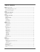
Table of Contents Preface About this User's Guide ....................................................................................................................... 5 What you will learn from this user's guide ......................................................................................................... 5 Conventions in this user's guide .........................................................................................................................
USB-1608G User's Guide Timer ................................................................................................................................................................ 20 Memory ............................................................................................................................................................ 20 Power .................................................................................................................................................
Preface About this User's Guide What you will learn from this user's guide This user's guide describes the Measurement Computing USB-1608G data acquisition device and lists device specifications. Conventions in this user's guide For more information Text presented in a box signifies additional information and helpful hints related to the subject matter you are reading.
Chapter 1 Introducing the USB-1608G The USB-1608G is a USB 2.0 high-speed device that provides the following features: 16 single-ended (SE) or eight differential (DIFF) analog input channels Eight individually configurable digital I/O channels Two counter channels (32-bit) that count TTL pulses One timer output channel (32-bit) Screw terminals for field wiring connections The USB-1608G is powered by the +5 volt USB supply from your computer; no external power is required.
Chapter 2 Installing the USB-1608G Unpacking As with any electronic device, you should take care while handling to avoid damage from static electricity. Before removing the device from its packaging, ground yourself using a wrist strap or by simply touching the computer chassis or other grounded object to eliminate any stored static charge. Contact us immediately if any components are missing or damaged.
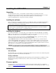
Chapter 3 Functional Details Analog input modes The USB-1608G device can acquire analog input data in two basic modes – software paced and hardware paced. Software paced You can acquire one analog sample at a time in software paced mode. You initiate the A/D conversion with a software command. The analog value is converted to digital data and returned to the computer. Repeat this procedure until you have the total number of samples that you want.
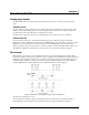
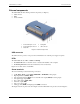
USB-1608G User's Guide Functional Details External components The USB-1608G has the following external components (see Figure 3): USB connector LEDs Screw terminals 1 2 3 Screw terminal pins 1 to 27 Screw terminal pins 28 to 54 Status LED 4 5 Activity LED USB connector Figure 3. External components USB connector The USB connector provides +5 V power and communication. No external power supply is required. LEDs The USB-1608G has two LEDs – Status and Activity.
USB-1608G User's Guide Functional Details Figure 4. SE mode pinout Figure 5.
USB-1608G User's Guide Functional Details Signal connections Analog input You can configure the analog inputs for SE or DIFF mode. The input voltage range is software selectable for ±10 V, ±5 V, ±2 V, or ±1 V. With SE mode, connect up to 16 inputs to screw terminals CH0 to CH15. SE mode requires two wires: Connect one wire to the signal you want to measure (CHx). Connect one wire to the analog ground reference ( AGND). Refer to Figure 4 on page 10 for the location of the SE inputs.
USB-1608G User's Guide Functional Details An example of a 4-element list is shown in the table below. Sample channel-gain queue list Element Channel Range Mode 0 1 2 3 CH5 CH1 CH15 CH5 BIP5V BIP10V BIP1V BIP5V SE DIFF SE SE Carefully match the gain to the expected voltage range on the associated channel or an over range condition may occur.
USB-1608G User's Guide 5. Functional Details Configure jumper W1 for either pull-up or pull-down. The jumper is configured by default for pull-down. Figure 8 shows the location of the jumper on the board. Figure 8. W1 jumper location Figure 9 shows the jumper configured for pull-up and pull-down. Figure 9. W1 jumper configurations 6. Replace the top section of the case, and fasten it to the bottom section with the four screws. Replace the rubber feet onto each screw.
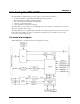
USB-1608G User's Guide Functional Details Timer output The TMR terminal is a pulse width modulation (PWM) timer output that can generate a pulse output with a programmable frequency in the range of 0.0149 Hz to 32 MHz. The timer output parameters are software selectable. Figure 10 shows the timer output schematic. Figure 10. Timer output schematic Power output The +5V terminal can output up to 10 mA maximum. You can use this terminal to supply power to external devices or circuitry.
USB-1608G User's Guide Functional Details Mechanical drawings Figure 11.
Chapter 4 Specifications All specifications are subject to change without notice. Typical for 25 °C unless otherwise specified. Specifications in italic text are guaranteed by design. Analog input Table 1.
USB-1608G User's Guide Specifications Accuracy Analog input DC voltage measurement accuracy Table 2. DC accuracy components and specifications. All values are (±) Range Gain error (% of reading) Offset error (µV) INL error (% of range) Absolute accuracy at Full Scale (µV) ±10 V ±5 V ±2 V ±1 V 0.024 0.024 0.024 0.024 915 686 336 245 0.0076 0.0076 0.0076 0.0076 4075 2266 968 561 Gain temperature coefficient (% reading/°C) Offset temperature coefficient (µV/°C) 0.0014 0.0014 0.0014 0.
USB-1608G User's Guide Specifications Digital input/output Table 6. Digital I/O specifications Parameter Specification Digital type Number of I/O Configuration Pull-up configuration CMOS 8 Each bit may be configured as input (power on default) or output The port has 47 kΩ resistors configurable as pull-ups or pull-downs (default) via internal jumper (W1). 33 to 8000 port reads/writes or single bit reads/writes per second typ, system dependent. 2.0 V min 5.5 V absolute max 0.8 V max –0.
USB-1608G User's Guide Specifications External clock input/output Table 8. External clock I/O specifications Parameter Specification Terminal names Terminal types AICKI, AICKO AICKI: Input, active on rising edge AICKO: Output, power on default is 0 V, active on rising edge AICKI: Receives sampling clock from external source AICKO: Outputs the internal A/D sampling clock, or the pulse generated from AICKI when in external clock mode.
USB-1608G User's Guide Specifications Timer Table 10. Timer specifications Parameter Specification Terminal name Timer type Output value Internal clock frequency Register widths High pulse width Low pulse width Output high voltage TMR PWM output with count, period, delay, and pulse width registers Default state is idle low with pulses high, software-selectable output invert 64 MHz 32-bit 15.625 ns min 15.625 ns min 4.4 V min (IOH = –50 µA) 3.76 V min (IOH = –2.5 mA) 0.1 V max (IOL = 50 µA) 0.
USB-1608G User's Guide Specifications Environmental Table 14. Environmental specifications Parameter Specification Operating temperature range Storage temperature range Humidity 0 °C to 55 °C max –40 °C to 85 °C max 0% to 90% non-condensing max Mechanical Table 15. Mechanical specifications Parameter Specification Dimensions (L × W × H) User connection length 127 × 89.9 × 35.6 mm (5.00 × 3.53 × 1.40 in.) 3 m (9.84 ft) max Screw terminal connector Table 16.
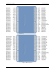
USB-1608G User's Guide Specifications Single-ended mode pinout Table 18.
Declaration of Conformity Manufacturer: Address: Category: Measurement Computing Corporation 10 Commerce Way Suite 1008 Norton, MA 02766 USA Electrical equipment for measurement, control and laboratory use.
Measurement Computing Corporation 10 Commerce Way Suite 1008 Norton, Massachusetts 02766 (508) 946-5100 Fax: (508) 946-9500 E-mail: info@mccdaq.com www.mccdaq.