
User Manual


USB-1408FS User's Guide Functional Details
12
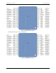
Signal connections
Analog input
You can connect up to eight analog input connections to the screw terminal containing pins 1 to 20 (CH0 IN
through
CH7 IN.)
You can configure the analog input channels as eight single-ended channels or four differential channels. When
configured for differential mode, each analog input has 14-bit resolution. When configured for single-ended
mode, each analog input has 13-bit resolution, due to restrictions imposed by the A/D converter.
Single-ended configuration
When all of the analog input channels are configured for single-ended input mode, eight analog channels are
available. The input signal is referenced to signal ground (
GND), and delivered through two wires:
Connect the wire carrying the signal to be measured to
CH# IN.
Connect the second wire to
AGND.
The input range for single-ended mode is ±10 V.
Single-ended measurements using differential channels
To perform a single-ended measurement using differential channels, connect the signal to the "CH# IN HI"
input, and ground the associated CH# IN LO input.
Differential configuration
When all of the analog input channels are configured for differential input mode, four analog channels are
available. In differential mode, the input signal is measured with respect to the low input.
The input signal is delivered through three wires:
Connect the wire carrying the signal to be measured to
CH# IN HI
Connect the wire carrying the reference signal to
CH# IN LO
Connect the third wire to
GND.
A low-noise precision programmable gain amplifier (PGA) is available on differential channels to provide gains
of up to 20 and a dynamic range of up to 14-bits. Differential mode input voltage ranges are ±20 V, ±10 V,
±5 V, ±4 V, ±2.5 V, ±2.0 V, ±1.25 V, and ±1.0 V.
In differential mode, the following two requirements must be met for linear operation:
Any analog input must remain in the −10V to +20V range with respect to ground at all times.
The maximum differential voltage on any analog input pair must remain within the selected voltage range.
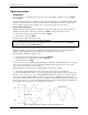
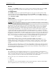
The input [common-mode voltage + signal] of the differential channel must be in the −10 V to +20 V range in
order to yield a useful result. For example, you input a 4 V pp sine wave to CHHI, and apply the same sine
wave 180° out of phase to CHLO. The common mode voltage is 0 V. The differential input voltage swings from
4 V− (−4 V) = 8 V to (−4 V) − 4 V = −8V. Both inputs satisfy the −10 V to +20 V input range requirement, and
the differential voltage is suited for the ±10 V input range (see Figure 5).
Figure 5. Differential voltage example: common mode voltage of 0 V