PCI-DAS1002 Multifunction Analog & Digital I/O User's Guide Document Revision 4, July, 2007 © Copyright 2007, Measurement Computing Corporation
Your new Measurement Computing product comes with a fantastic extra — Management committed to your satisfaction! Refer to www.mccdaq.com/execteam.html for the names, titles, and contact information of each key executive at Measurement Computing. Thank you for choosing a Measurement Computing product—and congratulations! You own the finest, and you can now enjoy the protection of the most comprehensive warranties and unmatched phone tech support.
Trademark and Copyright Information TracerDAQ, Universal Library, Harsh Environment Warranty, Measurement Computing Corporation, and the Measurement Computing logo are either trademarks or registered trademarks of Measurement Computing Corporation. Windows, Microsoft, and Visual Studio are either trademarks or registered trademarks of Microsoft Corporation LabVIEW is a trademark of National Instruments. CompactFlash is a registered trademark of SanDisk Corporation.
Table of Contents Preface About this User's Guide .......................................................................................................................7 What you will learn from this user's guide .........................................................................................................7 Conventions in this user's guide .........................................................................................................................7 Where to find more information ...
PCI-DAS1002 User's Manual Miscellaneous ...................................................................................................................................................22 Power consumption ..........................................................................................................................................22 Environmental ..................................................................................................................................................
Preface About this User's Guide What you will learn from this user's guide This user's guide explains how to install, configure, and use the PCI-DAS1002 so that you get the most out of its analog, digital, and timing I/O features. This user's guide also refers you to related documents available on our web site, and to technical support resources.
Chapter 1 Introducing the PCI-DAS1002 Overview: PCI-DAS1002 features This manual explains how to install and use the PCI-DAS1002. This board is a multifunction analog and digital I/O board designed for the PCI bus. The PCI-DAS1002 provides either 16 single-ended or eight differential analog inputs. Input ranges are software-selectable as either bipolar or unipolar. Analog input ranges for the PCI-DAS1002 are software programmable for the following ranges: Bipolar: ±10 V, ±5 V, ±2.5 V, and ±1.
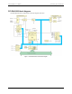
PCI-DAS1002 User's Manual Introducing the PCI-DAS1002 PCI-DAS1002 block diagram PCI-DAS1002 functions are illustrated in the block diagram shown here. Figure 1.
Chapter 2 Installing the PCI-DAS1002 What is included with your PCI-DAS1002 As you unpack your board, make sure each of the items shown below is included: Hardware PCI-DAS1002 Additional documentation In addition to this hardware user's guide, you should also receive the Quick Start Guide (available in PDF at www.mccdaq.com/PDFmanuals/DAQ-Software-Quick-Start.pdf).
PCI-DAS1002 User's Manual Installing the PCI-DAS1002 Signal termination and conditioning accessories MCC provides signal termination and conditioning products for use with the PCI-DAS1002. Refer to the "Field wiring and signal termination" section for a complete list of compatible accessory products. Unpacking the PCI-DAS1002 As with any electronic device, you should take care while handling to avoid damage from static electricity.
PCI-DAS1002 User's Manual Installing the PCI-DAS1002 Configuring the hardware All hardware configuration options on the PCI-DAS1002 are software controlled. You can select some of the configuration options using InstaCal, such as the analog input configuration (16 single-ended or eight differential channels), and the source for the two independent counters. Once selected, any program that uses the Universal Library will initialize the hardware according to these selections.
PCI-DAS1002 User's Manual Installing the PCI-DAS1002 Pinout – main I/O connector 8-channel differential mode Signal Name GND N/C N/C N/C N/C A/D Int.
PCI-DAS1002 User's Manual Installing the PCI-DAS1002 16-channel single-ended mode Signal Name GND N/C N/C N/C N/C A/D Int.
PCI-DAS1002 User's Manual Installing the PCI-DAS1002 Cables Cable is labeled “Pins 1-50”. 50 49 50 1 2 Key 100 The red stripe identifies pin # 1 99 100 1 51 Key 51 Cable is labeled “Pins 51-100”. 52 The red stripe identifies pin # 51 Figure 2. C100FF-x cable Field wiring and signal termination The following MCC screw terminal and signal conditioning boards are compatible with the PCI-DAS1002: SCB-50 – 50-conductor, shielded signal connection box.
Chapter 3 Programming and Developing Applications After following the installation instructions in Chapter 2, your board should now be installed and ready for use. Although the board is part of the larger DAS family, in general there may be no correspondence among registers for different boards. Software written at the register level for other DAS models will not function correctly with your board.
Chapter 4 Calibrating the Board Introduction Calibrate the board using the InstaCal utility after the board has fully warmed up. The recommended warm-up time is 15 minutes. For best results, calibrate the board immediately before making critical measurements. The high resolution analog components on the board are sensitive to temperature. Pre-measurement calibration ensures that your board is operating at optimum calibration values.
Chapter 5 Specifications Typical for 25 °C unless otherwise specified. Specifications in italic text are guaranteed by design. Analog input Table 1. Analog input specifications Parameter Specification A/D converter type Resolution Number of channels Input ranges ADS7800 or equivalent 12 bits 16 single-ended / 8 differential, software selectable ±10 V, ±5 V, ±2.5 V, ±1.25 V, 0 to 10 V, 0 to 5V, 0 to 2.5 V, 0 to 1.25 V software programmable Internal counter - 82C54.
PCI-DAS1002 User's Manual Specifications Accuracy Accuracies are listed for a 200 kHz sampling rate, 100 sample average, single channel operation, a 15 minute warm-up, and operational temperatures within ±2 °C of internal calibration temperature. The calibrator test source high side is tied to Channel 0 In and the low side is tied to AGND. Table 2. Absolute accuracy specifications (analog input) Range Absolute Accuracy ±10.00 V ±5.000 V ±2.500 V ±1.250 V 0 to 10.00 V 0 to 5.000 V 0 to 2.500 V 0 to 1.
PCI-DAS1002 User's Manual Specifications Analog output Table 6. Analog output specifications D/A converter type Resolution Number of channels Configuration Output range D/A pacing Data transfer Monotonicity Overall analog output drift Settling time Slew rate Current drive Output short-circuit duration Output coupling Output impedance Miscellaneous AD7847AR or equivalent 12 bits 2 Voltage output, single-ended ±10 V, ±5 V, 0 to 10 V, or 0 to 5 V. Software selectable.
PCI-DAS1002 User's Manual Specifications Counters Table 9. Counter specifications Parameter Specification Counter type Configuration 82C54A: Counter 0 - ADC residual sample counter 82C54 Two 82C54 devices.
PCI-DAS1002 User's Manual Specifications Digital input/output Table 10. DIO specifications Digital type Number of I/O Configuration Input high voltage Input low voltage Output high voltage (IOH = -2.5 mA) Output low voltage (IOL = 2.5 mA) Power-up / reset state 82C55 24 (FIRSTPORTA Bit 0 through FIRSTPORTC Bit 7) 2 banks of 8 and 2 banks of 4 or 3 banks of 8 or 2 banks of 8 with handshake 2.0 V min, 5.5 V absolute max 0.8 V max, –0.5 V absolute min 3.0 V min 0.
PCI-DAS1002 User's Manual Specifications Connector and pin out Table 16. Main connector specifications Connector type Compatible cable Compatible accessory products (with C100FF-x cable) 100-pin high-density Robinson Nugent C100FF-x, unshielded ribbon cable.
PCI-DAS1002 User's Manual Specifications 16-channel single-ended mode pin out Pin 1 2 3 4 5 6 7 8 9 10 11 12 13 14 15 16 17 18 19 20 21 22 23 24 25 26 27 28 29 30 31 32 33 34 35 36 37 38 39 40 41 42 43 44 45 46 47 48 49 50 Signal Name LLGND CH0 HI CH8 HI CH1 HI CH9 HI CH2 HI CH10 HI CH3 HI CH11 HI CH4 HI CH12 HI CH5 HI CH13 HI CH6 HI CH14 HI CH7 HI CH15 HI LLGND N/C N/C N/C N/C N/C N/C N/C N/C N/C N/C N/C N/C N/C N/C N/C N/C D/A GND 0 D/A OUT 0 D/A GND 1 D/A OUT 1 CTR4 CLK CTR4 GATE CTR4 OUT A/D EXTERNAL
Declaration of Conformity Manufacturer: Address: Category: Measurement Computing Corporation 10 Commerce Way Suite 1008 Norton, MA 02766 USA Electrical equipment for measurement, control and laboratory use.
Measurement Computing Corporation 10 Commerce Way Suite 1008 Norton, Massachusetts 02766 (508) 946-5100 Fax: (508) 946-9500 E-mail: info@mccdaq.com www.mccdaq.