PCI-DIO24 24-bit, Logic-level Digital I/O Board User's Guide Document Revision 2, June, 2006 © Copyright 2006, Measurement Computing Corporation
Your new Measurement Computing product comes with a fantastic extra — Management committed to your satisfaction! Refer to www.mccdaq.com/execteam.html for the names, titles, and contact information of each key executive at Measurement Computing. Thank you for choosing a Measurement Computing product—and congratulations! You own the finest, and you can now enjoy the protection of the most comprehensive warranties and unmatched phone tech support.
Trademark and Copyright Information TracerDAQ, Universal Library, InstaCal, Harsh Environment Warranty, Measurement Computing Corporation, and the Measurement Computing logo are either trademarks or registered trademarks of Measurement Computing Corporation. Windows, Microsoft, and Visual Studio are either trademarks or registered trademarks of Microsoft Corporation LabVIEW is a trademark of National Instruments. CompactFlash is a registered trademark of SanDisk Corporation.
Table of Contents Preface About this User's Guide .......................................................................................................................v What you will learn from this user's guide .........................................................................................................v Conventions in this user's guide........................................................................................................................................
Preface About this User's Guide What you will learn from this user's guide This user's guide explains how to install, configure, and use the PCI-DIO24 so that you get the most out of the digital I/O features. This user's guide also refers you to related documents available on our web site, and to technical support resources. Conventions in this user's guide For more information on … Text presented in a box signifies additional information and helpful hints related to the subject matter you are reading.
Chapter 1 Introducing the PCI-DIO24 This manual explains how to install, configure and use the PCI-DIO24 digital I/O board. The PCI-DIO24 provides 24 lines of digital I/O. An on-board, industry standard 82C55 programmable peripheral interface chip provides the 24 digital I/O lines in three eight-bit ports (Port A, Port B, and Port C). Port C can be further divided into two four-bit ports (Port C-HI and Port C-LO). You can configure each port independently for either input or output.
PCI-DIO24 User's Guide Introducing the PCI-DIO24 Software features For information on the features of InstaCal and the other software included with your PCI-DIO24, refer to the Quick Start Guide that shipped with your device. The Quick Start Guide is also available in PDF at www.mccdaq.com/PDFmanuals/DAQ-Software-Quick-Start.pdf. Check www.mccdaq.com/download.htm for the latest software version or versions of the software supported under less commonly used operating systems.
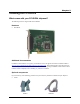
Chapter 2 Installing the PCI-DIO24 What comes with your PCI-DIO24 shipment? The following items are shipped with the PCI-DIO24. Hardware ! PCI-DIO24 Additional documentation In addition to this hardware user's guide, you should also receive the Quick Start Guide (available in PDF at www.mccdaq.com/PDFmanuals/DAQ-Software-Quick-Start.pdf). This booklet supplies a brief description of the software you received with your PCI-DIO24 and information regarding installation of that software.
PCI-DIO24 User's Guide ! Installing the PCI-DIO24 Signal termination and conditioning accessories MCC provides signal termination products for use with the PCI-DIO24. Refer to the "Field wiring and signal termination" section on page 2-4 for a complete list of compatible accessory products. Unpacking the PCI-DIO24 As with any electronic device, you should take care while handling to avoid damage from static electricity.
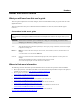
PCI-DIO24 User's Guide Installing the PCI-DIO24 Connecting the board for I/O operations Connectors, cables – main I/O connector Table 2-1 lists the board connector type, applicable cables, and compatible accessory products for the PCIDIO24. Table 2-1. Board connectors, cables, and accessory equipment Connector type Compatible cables Compatible accessory products (with the C37FF-x or C37FFS-x cable) 37-pin D-type C37FF-x unshielded ribbon cable. x = length in feet.
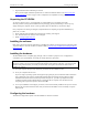
PCI-DIO24 User's Guide Installing the PCI-DIO24 Information on signal connections General information regarding signal connection and configuration is available in the Guide to Signal Connections. This document is available on our web site at www.mccdaq.com/signals/signals.pdf. Cabling The red stripe identifies pin # 1 1 1 20 20 37 37 19 19 Figure 2-2. C37FF-x cable 1 19 1 20 37 19 20 37 Figure 2-3.
PCI-DIO24 User's Guide ! ! ! Installing the PCI-DIO24 CIO-ERB08 — Eight-channel electromechanical relay accessory for digital I/O boards. Details on this product are available on our web site at www.mccdaq.com/cbicatalog/cbiproduct.asp?dept_id=123&pf_id=241. CIO-SERB08 — Eight Form C and ten socketed relay accessory for digital I/O boards. Details on this product are available on our web site at www.mccdaq.com/cbicatalog/cbiproduct.asp?dept_id=123&pf_id=680.
Chapter 3 Programming and Developing Applications After following the installation instructions in Chapter 2, your board should now be installed and ready for use. Programming languages Measurement Computing’s Universal Library™ provides access to board functions from a variety of Windows programming languages.
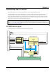
Chapter 4 Functional Details DIO signals All digital outputs and inputs on the PCI-DIO24 are CMOS TTL. Voltages and currents associated with external devices are usually far greater than can be supplied from a PCI-DIO24. Caution! Direct connections to high-current/high voltage devices will damage the board. The 82C55 digital I/O chip initializes all ports as inputs on power-up and reset. The state of the digital I/O lines is not defined as either logic high or logic low when in input mode.
PCI-DIO24 User's Guide HI HI n6 n6 n4 n3 n1 User Connector Digital I/O Lines n7 n2 n = A, B, or C COM n7 n5 Digital I/O Port +5 VDC Dot indicates the common line 2.2 K SIP 2.2 K SIP User Connector Digital I/O Lines +5 VDC Functional Details n5 Digital I/O Port n4 n3 n2 n = A, B, or C n1 n0 n0 LO (GND) LO (GND) COM Dot indicates the common line 2.2 K SIP installed for pull-up 2.2 K SIP installed for pull-down Figure 4-2.
Chapter 5 Specifications Typical for 25 °C unless otherwise specified. Specifications in italic text are guaranteed by design. Power consumption Table 1. Power consumption specifications +5V operating 240 typical, 350 max Digital input / output Table 2.
PCI-DIO24 User's Guide Specifications Main connector and pin out Table 4. Board connector, cables, and accessory equipment Connector type Compatible cables Compatible accessory products (with the C37FF-x or C37FFS-x cable) 37-pin D-type C37FF-x unshielded ribbon cable. x = length in feet. C37FFS-x cable shielded round cable. x = length in feet. SCB-37 CIO-MINI37 CIO-MINI37-VERT CIO-ERB08 CIO-SERB08 CIO-ERB24 CIO-SPADE50 SSR-RACK08 SSR-RACK24 Table 5.
Declaration of Conformity Manufacturer: Address: Category: Measurement Computing Corporation 10 Commerce Way Suite 1008 Norton, MA 02766 USA Electrical equipment for measurement, control and laboratory use.
Measurement Computing Corporation 10 Commerce Way Suite 1008 Norton, Massachusetts 02766 (508) 946-5100 Fax: (508) 946-9500 E-mail: info@mccdaq.com www.mccdaq.