i
PCI-QUAD-AC5 High Output Digital I/O Board User’s Guide Document Revision 2, July, 2005 © Copyright 2005, Measurement Computing Corporation
Your new Measurement Computing product comes with a fantastic extra — Management committed to your satisfaction! Refer to www.mccdaq.com/execteam.html for the names, titles, and contact information of each key executive at Measurement Computing. Thank you for choosing a Measurement Computing product—and congratulations! You own the finest, and you can now enjoy the protection of the most comprehensive warranties and unmatched phone tech support.
Trademark and Copyright Information TracerDAQ, Universal Library, InstaCal, Harsh Environment Warranty, Measurement Computing Corporation, and the Measurement Computing logo are either trademarks or registered trademarks of Measurement Computing Corporation. SoftWIRE is a registered trademark of SoftWIRE Technology, Inc. Windows, Microsoft, and Visual Studio are either trademarks or registered trademarks of Microsoft Corporation LabVIEW is a trademark of National Instruments.
Table of Contents Preface About this User's Guide .......................................................................................................................v What you will learn from this user's guide .........................................................................................................v Conventions in this user's guide .........................................................................................................................v Where to find more information....
Preface About this User's Guide What you will learn from this user's guide This user's guide explains how to install, configure, and use the PCI-QUAD-AC5 board so that you get the most out of its digital I/O features. This user's guide also refers you to related documents available on our web site, and to technical support resources.
PCI-QUAD-AC5 User's Guide About this User's Guide Where to find more information The following electronic documents provide helpful information relevant to the operation of the PCIQUAD-AC5. MCC's Specifications: PCI-QUAD-AC5 (the PDF version of Chapter 6 in this guide) is available on our web site at www.mccdaq.com/pdfs/PCI-QUAD-AC5.pdf. MCC's Register Map for the PCI-QUAD-AC5 Series is available on our web site at www.mccdaq.com/registermaps/RegMapPCI-QUAD-AC5.
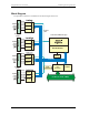
Chapter 1 Introducing the PCI-QUAD-AC5 Overview: PCI-QUAD-AC5 features The PCI-QUAD-AC5 is a 96-bit, high output, digital I/O board for PCI-compatible computers. Primarily designed as a direct interface to the industry-standard SSR-PB24 rack, the board is also highly useful as a general purpose digital I/O board. The 96-bits of digital I/O are organized into four 24-bit groups based on an 82C55 mode 0 emulation (no strobed I/O or bi-directional I/O bits).
PCI-QUAD-AC5 User's Guide Introducing the PCI-QUAD-AC5 Block Diagram PCI-QUAD-AC5 functions are illustrated in the block diagram shown here.
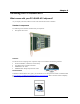
Chapter 2 Installing the PCI-QUAD-AC5 What comes with your PCI-QUAD-AC5 shipment? As you unpack your board, make sure each of the items shown below is included: Standard components The following items should be included with your shipment: PCI-QUAD-AC5 board Software The Measurement Computing Data Acquisition Software CD contains the following software: InstaCal installation, calibration, and test utility TracerDAQ suite of virtual instruments SoftWIRE for VS .
PCI-QUAD-AC5 User's Guide Installing the PCI-QUAD-AC5 Optional components You can also order the following MCC products to use with your PCI-QUAD-AC5. Cables C50FE-x C50FF-x Signal termination and conditioning accessories MCC provides signal conditioning and termination products for use with the PCI-QUAD-AC5. Refer to Field wiring and signal termination on page 2-6 for a complete list of compatible accessory products. If any items are missing or damaged, notify Measurement Computing Corp.
PCI-QUAD-AC5 User's Guide Installing the PCI-QUAD-AC5 Installing the software Install the software included with your board before you install the hardware. Installing the software first ensures that the information required for proper board detection is installed and available at boot up. Refer to the Quick Start Guide for instructions on installing the software on the Measurement Computing Data Acquisition Software CD. This booklet is shipped with the hardware, and is also available in PDF at www.
PCI-QUAD-AC5 User's Guide Installing the PCI-QUAD-AC5 Connecting the board for I/O operations Connectors, cables – main I/O connector Table 2-1 lists the board connectors, applicable cables, and compatible accessory products for the PCIQUAD-AC5. Table 2-1. Board connector, cables, and accessory equipment Connector type Compatible cables Compatible accessory products (with the C50FE-x cable) Compatible accessory products (with the C50FF-x cable) Four, male 50-pin 0.
PCI-QUAD-AC5 User's Guide Installing the PCI-QUAD-AC5 Signal Connector ports/bits Plug Port P1 P2 P3 P4 1st 2nd 3rd 4th Bits 1 to 24 25 to 48 49 to 72 73 to 96 Pin Port C Bit 7 Port C Bit 6 Port C Bit 5 Port C Bit 4 Port C Bit 3 Port C Bit 2 Port C Bit 1 Port C Bit 0 Port B Bit 7 Port B Bit 6 Port B Bit 5 Port B Bit 4 Port B Bit 3 Port B Bit 2 Port B Bit 1 Port B Bit 0 Port A Bit 7 Port A Bit 6 Port A Bit 5 Port A Bit 4 Port A Bit 3 Port A Bit 2 Port A Bit 1 Port A Bit 0 +5V OUT P1 - P4 Pin 1 3 5
PCI-QUAD-AC5 User's Guide Installing the PCI-QUAD-AC5 Field wiring and signal termination You can use the following screw terminal boards to terminate field signals and route them into the PCIQUAD-AC5 using the C50FF-x cable. CIO-MINI50 – 50-pin universal screw terminal board. Four boards are required. Details on this product are available on our web site at www.mccdaq.com/cbicatalog/cbiproduct.asp?dept_id=102&pf_id=258.
Chapter 3 Programming and Developing Applications After following the installation instructions in Chapter 2, your board should now be installed and ready for use. In general there may be no correspondence among registers for different boards. Software written at the register level for other models will not function correctly with your board. Programming languages Measurement Computing’s Universal Library® provides access to board functions from a variety of Windows programming languages.
Chapter 4 Functional Details Signal connections All digital inputs and outputs on the PCI-QUAD-AC5 connector are TTL and are fully compatible with the inputs and outputs on the industry-standard PB-24 rack (Measurement Computing Corporation's model SSR-PB24). 82C55 emulation The PCI-QUAD-AC5 board emulates the 82C55 chip. The 82C55 emulation initializes all ports as inputs on power-up and reset. A TTL input is a high impedance input.
PCI-QUAD-AC5 User's Guide Functional Details The PCI-QUAD-AC5 board has open locations where you can install a 2.2 K ohm, eight-resistor single inline package (SIP) resistor network for each port. Each of the four port locations is identified by the bit range — the First Port connector (P1) is labeled Bits 1 to 24, the Second Port connector (P2) is labeled Bits 25 to 48, the Third Port connector (P3) is labeled Bits 49 to 72, and the Fourth Port connector (P4) is labeled Bits 73 to 96.
PCI-QUAD-AC5 User's Guide Functional Details Unconnected inputs float Unconnected inputs typically float high, but not reliably. If you are using a PCI-QUAD-AC5 board for input and have unconnected inputs, ignore the data from those lines. You do not have to terminate input lines, and unconnected lines will not affect the performance of connected lines. Ensure that you mask out any unconnected bits in software.
Chapter 5 Specifications Typical for 25 °C unless otherwise specified. Specifications in italic text are guaranteed by design. Power consumption +5V 2.4 A typical, 3.
PCI-QUAD-AC5 User's Guide Specifications P1 Pin 1 3 5 7 9 11 13 15 17 19 21 23 25 27 29 31 33 35 37 39 41 43 45 47 49 Signal Name FIRST PORT C Bit 7 FIRST PORT C Bit 6 FIRST PORT C Bit 5 FIRST PORT C Bit 4 FIRST PORT C Bit 3 FIRST PORT C Bit 2 FIRST PORT C Bit 1 FIRST PORT C Bit 0 FIRST PORT B Bit 7 FIRST PORT B Bit 6 FIRST PORT B Bit 5 FIRST PORT B Bit 4 FIRST PORT B Bit 3 FIRST PORT B Bit 2 FIRST PORT B Bit 1 FIRST PORT B Bit 0 FIRST PORT A Bit 7 FIRST PORT A Bit 6 FIRST PORT A Bit 5 FIRST PORT A Bit 4
PCI-QUAD-AC5 User's Guide Specifications P3 Pin 1 3 5 7 9 11 13 15 17 19 21 23 25 27 29 31 33 35 37 39 41 43 45 47 49 Signal Name THIRD PORT C Bit 7 THIRD PORT C Bit 6 THIRD PORT C Bit 5 THIRD PORT C Bit 4 THIRD PORT C Bit 3 THIRD PORT C Bit 2 THIRD PORT C Bit 1 THIRD PORT C Bit 0 THIRD PORT B Bit 7 THIRD PORT B Bit 6 THIRD PORT B Bit 5 THIRD PORT B Bit 4 THIRD PORT B Bit 3 THIRD PORT B Bit 2 THIRD PORT B Bit 1 THIRD PORT B Bit 0 THIRD PORT A Bit 7 THIRD PORT A Bit 6 THIRD PORT A Bit 5 THIRD PORT A Bit 4
EC Declaration of Conformity We, Measurement Computing Corporation, declare under sole responsibility that the product PCI-QUAD-AC5 Part Number 96-bit, high drive digital I/O board with AC5 and PB24 interface Description to which this declaration relates, meets the essential requirements, is in conformity with, and CE marking has been applied according to the relevant EC Directives listed below using the relevant section of the following EC standards and other informative documents: EU EMC Di
Measurement Computing Corporation 16 Commerce Boulevard, Middleboro, Massachusetts 02346 (508) 946-5100 Fax: (508) 946-9500 E-mail: info@mccdaq.com www.mccdaq.