USB-1616HS-2 User's Guide Document Revision 1, August, 2007 © Copyright 2007, Measurement Computing Corporation
Your new Measurement Computing product comes with a fantastic extra — Management committed to your satisfaction! Refer to www.mccdaq.com/execteam.html for the names, titles, and contact information of each key executive at Measurement Computing. Thank you for choosing a Measurement Computing product—and congratulations! You own the finest, and you can now enjoy the protection of the most comprehensive warranties and unmatched phone tech support.
Trademark and Copyright Information TracerDAQ, Universal Library, Harsh Environment Warranty, Measurement Computing Corporation, and the Measurement Computing logo are either trademarks or registered trademarks of Measurement Computing Corporation. Windows, Microsoft, and Visual Studio are either trademarks or registered trademarks of Microsoft Corporation LabVIEW is a trademark of National Instruments. CompactFlash is a registered trademark of SanDisk Corporation.
Table of Contents Preface About this User's Guide .......................................................................................................................7 What you will learn from this user's guide .........................................................................................................7 Conventions used in this user's guide .................................................................................................................7 Where to find more information ......
USB-1616HS-2 User's Guide Tips for making high-speed counter measurements (> 1 MHz) .......................................................................................27 Mapped channels .............................................................................................................................................................27 Counter modes ...................................................................................................................................................
Preface About this User's Guide What you will learn from this user's guide This user's guide explains how to install, configure, and use the USB-1616HS-4 so that you get the most out of its analog I/O, thermocouple (TC) input, digital I/O, counter/timer I/O features. This user's guide also refers you to related documents available on our web site, and to technical support resources.
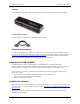
Chapter 1 Introducing the USB-1616HS-2 Overview: USB-1616HS-2 features The USB-1616HS-2 is supported under popular Microsoft® Windows® operating systems. The USB-1616HS-2 board is a multifunction measurement and control board designed for the USB bus. The USB-1616HS-2 provides either eight differential or 16 single-ended analog inputs with 16-bit resolution. It offers seven software-selectable analog input ranges of ±10 V, ±5 V, ±2 V, ±1 V, ±0.5 V, ±0.2 V, and ±0.1V.
Chapter 2 Installing the USB-1616HS-2 What comes with your USB-1616HS-2 shipment? As you unpack your USB-1616HS-2, verify that the following components are included. Hardware USB-1616HS-2 USB cable (2-meter length) TR-2U power supply and CA-1* line cord AC-to-DC conversion power supply and cord plugs into the external power connector of the USB-1616HS-2. * European customers: Contact Measurement Computing to order the CA-261 line cord for your region.
USB-1616HS-2 User's Guide Installing the USB-1616HS-2 AI-EXP48 Analog input expansion module adds up to 24 differential or 48 single-ended inputs to the USB-1616HS-2. CA-96A expansion cable Expansion cable for connecting to the AI-EXP48 expansion board. Additional documentation In addition to this hardware user's guide, you should also receive the Quick Start Guide (available in PDF at www.mccdaq.com/PDFmanuals/DAQ-Software-Quick-Start.pdf).
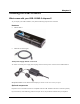
USB-1616HS-2 User's Guide Installing the USB-1616HS-2 Installing the hardware To connect the USB-1616HS-2 to your system, turn your computer on, and then do the following: Connect signal lines to the USB-1616HS-2's removable screw terminal blocks. o Connect voltage signals as single-ended or differential connections (see Figure 1). o Connect thermocouple signals as differential connections (see Figure 1).
USB-1616HS-2 User's Guide Installing the USB-1616HS-2 Configuring the hardware All hardware configuration options on the USB-1616HS-2 are software-controlled. You can select some of the configuration options using InstaCal, such as the analog input configuration (16 single-ended or 8 differential channels), and the edge used for pacing when using an external clock. When measuring from thermocouples, make sure you configure the channels for differential mode.
USB-1616HS-2 User's Guide Installing the USB-1616HS-2 Screw terminal pin outs Analog In Analog common (Ad) CH 4 (4H) CH 12 (12L) Analog common (Ad) CH 5 (5H) CH 13 (13L) Analog common (Ad) CH 6 (6H) CH 14 (14L) Analog common (Ad) CH 7 (7H) CH 15 (15L) 13 Port B Analog In Analog common (Ad) CH 0 (0H) CH 8 (8L) Analog common (Ad) CH 1 (1H) CH 9 (9L) Analog common (Ad) CH 2 (2H) CH 10 (10L) Analog common (Ad) CH 3 (3H) CH 11 (11L) Port C Analog Out Analog common (Ad) Analog output 0 (AO0) Analog out
USB-1616HS-2 User's Guide Installing the USB-1616HS-2 USB-1616HS-2 screw terminal pin out – differential connections Analog In Analog common (Ab) CH 4 HI (4H) CH 4 LO (12L) Analog common (Ab) CH 5 HI (5H) CH 5 LO (13L) Analog common (Ab) CH 6 HI (6H) CH 6 LO (14L) Analog common (Ab) CH 7 HI (7H) CH 7 LO (15L) Port A Port B Analog In Analog common (Ab) CH 0 HI (0H) CH 0 LO (8L) Analog common (Ab) CH 1 HI (1H) CH 1 LO (9L) Analog common (Ab) CH 2 HI (2H) CH 2 LO (10L) Analog common (Ab) CH 3 HI (3H) CH
USB-1616HS-2 User's Guide Installing the USB-1616HS-2 Cabling Use a CA-96A 25-pin expansion cable (CA-96A expansion cable) to connect to the USB-1616HS-2's 25-pin expansion connector. Figure 3.
Chapter 3 Functional Details This chapter contains detailed information on all of the features available from the board, including: a diagram and explanations of physical board components a functional block diagram information on how to use the signals generated by the board diagrams of signals using default or conventional board settings USB-1616HS-2 components These USB-1616HS-2 components are shown in Figure 4.
USB-1616HS-2 User's Guide Functional Details Device "Active" LED Counter and digital I/O (port C) screw terminal blocks External "Power" LED Counter and digital I/O (port B) screw terminal blocks USB connector Timer and digital I/O (port A) screw terminal blocks External power connector Figure 5.
USB-1616HS-2 User's Guide Functional Details USB-1616HS-2 block diagram Figure 6 shows a simplified block diagram of the USB-1616HS-2. This board provides all of the functional elements shown in the figure.
USB-1616HS-2 User's Guide Functional Details Analog input The USB-1616HS-2 has a 16-bit, 1-MHz A/D coupled with 16 single-ended, or eight differential analog inputs. Seven software programmable ranges provide inputs from ±10 V to ±100 mV full scale. Analog input scanning The USB-1616HS-2 has several scanning modes to address various applications. You can load the 512-location scan buffer with any combination of analog input channels.
USB-1616HS-2 User's Guide Functional Details If you want 256 oversamples, then each analog channel in the scan group will take 256 µs, and the returned 16bit value represents an average of 256 consecutive 1 µs samples of that channel. The acquisition is triggered and 16-bit values—each representing an average of 256—stream to the PC via the USB cable.
USB-1616HS-2 User's Guide Functional Details The counter channels may return only the lower 16-bits of count value if that is sufficient for the application. They could also return the full 32-bit result if necessary. Similarly, the digital input channel could be the full 24 bits if desired or only eight bits if that is sufficient.
USB-1616HS-2 User's Guide Functional Details Thermocouple input You can configure up to eight analog inputs in differential mode on the USB-1616HS-2 to accept a thermocouple (TC) input. Built-in cold-junction sensors are provided for each of the screw-terminal connectors, and any TC type can be attached to any of the eight thermocouple channels.
USB-1616HS-2 User's Guide Functional Details Although averaging can be effective, it suffers from several drawbacks: Noise in measurements only decreases as the square root of the number of measurements—reducing RMS noise significantly may require many samples. Thus, averaging is suited to low-speed applications that can provide many samples. Only random noise is reduced or eliminated by averaging. Averaging does not reduce or eliminate periodic signals.
USB-1616HS-2 User's Guide Functional Details Due to the time it takes to shift the digital data out to the DACs, plus the actual settling time of the digital-toanalog conversion, the DACs actually take up to 4 µs after the start of scan to settle on the updated value. The data for the DACs and pattern digital output comes from a PC-based buffer. The data is streamed across the USB2 bus to the USB-1616HS-2.
USB-1616HS-2 User's Guide Functional Details Hardware analog triggering The USB-1616HS-2 uses true analog triggering in which the trigger level you program sets an analog DAC, which is then compared in hardware to the analog input level on the selected channel. This guarantees an analog trigger latency that is less than 1 µs. You can select any analog channel as the trigger channel, but the selected channel must be the first channel in the scan.
USB-1616HS-2 User's Guide Functional Details Software-based triggering usually results in a long period of inactivity between the trigger condition being detected and the data being acquired. However, the USB-1616HS-2 avoids this situation by using pre-trigger data.
USB-1616HS-2 User's Guide Functional Details When reading synchronously, all counters are set to zero at the start of an acquisition. When reading asynchronously, counters may be cleared on each read, count up continually, or count until the 16-bit or 32-bit limit has been reached. See counter mode explanations below. Figure 12. Typical USB-1616HS-2 counter channel Tips for making high-speed counter measurements (> 1 MHz) Use coax or twisted-pair wire. Connect one side to Digital Common.
USB-1616HS-2 User's Guide Functional Details The counter rolls over on the 16-bit (counter low) boundary, or on the 32-bit (counter high) boundary. Clear on read mode The counter counts up and is cleared after each read. By default, the counter counts up and only clears the counter at the start of a new scan command. The final value of the counter—the value just before it was cleared—is latched and returned to the USB-1616HS-2.
USB-1616HS-2 User's Guide Functional Details There are 16 different debounce times. In either debounce mode, the debounce time selected determines how fast the signal can change and still be recognized. The two debounce modes are trigger after stable and trigger before stable. A discussion of the two modes follows. Figure 13.
USB-1616HS-2 User's Guide Functional Details Figure 15. Debounce module – Trigger before stable mode The following time periods (T1 through T6) pertain to the above drawing. T1 – In the illustrated example, the input signal is low for the debounce time (equal to T1); therefore when the input edge arrives at the end of time period T1, it is accepted and the output (of the debounce module) goes high. Note that a period of stability must precede the edge in order for the edge to be accepted.
USB-1616HS-2 User's Guide Functional Details Use trigger before stable mode when the input signal has groups of glitches and each group is to be counted as one. The trigger before stable mode recognizes and counts the first glitch within a group but rejects the subsequent glitches within the group if the debounce time is set accordingly. The debounce time should be set to encompass one entire group of glitches as shown in the following diagram. Figure 17.
USB-1616HS-2 User's Guide Functional Details debounced from 500 ns to 25.5 ms (total of 16 selections) to eliminate extraneous noise or switch induced transients. Encoder input signals must be within -5V to +10V and the switching threshold is TTL (1.3V). Quadrature encoders generally have three outputs: A, B, and Z. The A and B signals are pulse trains driven by an optical sensor inside the encoder. As the encoder shaft rotates, a laminated optical shield rotates inside the encoder.
USB-1616HS-2 User's Guide Functional Details Maximizing encoder accuracy If there are 512 pulses on A, then the encoder position is accurate to within 360°/512. You can get even greater accuracy by counting not only rising edges on A but also falling edges on A, giving position accuracy to 360 degrees/1024. You get maximum accuracy counting rising and falling edges on A and on B (since B also has 512 pulses.) This gives a position accuracy of 360°/2048. These different modes are known as X1, X2, and X4.
USB-1616HS-2 User's Guide Functional Details Each signal (A, B) can be connected as a single-ended connection with respect to the common digital ground (GND). Both encoders need power from an external power source (typically +5 VDC). Connect each encoder's power input to the external power source. Connect the return to digital common (GND) on the same source.
USB-1616HS-2 User's Guide Functional Details Both timer outputs can also be updated during an acquisition as the result of setpoints applied to analog or digital inputs. Using multiple USB-1616HS-2s per PC USB-1616HS-2 features can be replicated up to four times, as up to four devices can be connected to a single host PC. The serial number on each USB-1616HS-2 distinguishes one from another. You can operate multiple USB-1616HS-2 boards synchronously.
USB-1616HS-2 User's Guide Criteria – input signal is equal to X Compare X to: Setpoint definition (choose one) Limit A or Limit B Equal to A (X = A) Below A (X < A) Above B (X > B) Window* (non-hyste resis mode) Inside (B < X < A) Outside ( B > X; or, X > A) Window* (hysteresis mode) Above A (X > A) Below (A < X < B) (Both conditions are checked when in hysteresis mode Functional Details Action - driven by condition Update conditions: True only: If True, then output value 1 If Fa
USB-1616HS-2 User's Guide Functional Details Setpoint configuration You program all setpoints as part of the pre-acquisition setup, similar to setting up an external trigger. Since each setpoint acts on 16-bit data, each has two 16-bit compare values: a high limit (limit A) and a low limit (limit B). These limits define the setpoint window. There are several possible conditions (criteria) and effectively three update modes, as explained in the following configuration summary.
USB-1616HS-2 User's Guide Functional Details A value of 0 indicates that the setpoint criteria are not met—in other words, the condition is False. A value of 1 indicates that the criteria have been met—in other words, the condition is True. In the following example, the criteria for setpoints 0, 1, and 4 is satisfied (True), but the criteria for the other 13 setpoints has not been met.
USB-1616HS-2 User's Guide Functional Details Figure 26. Analog inputs with setpoints update on True and False In the channel 5 example, the setpoint placed on analog Channel 5 updated DAC1 with 0.0 V. The update occurred when channel 5's input was less than the setpoint (limit A). When the value of channel 5's input was above setpoint limit A, the condition of
USB-1616HS-2 User's Guide Functional Details Figure 27. Timer output update on True and False Using the hysteresis function Update mode: N/A, the hysteresis option has a forced update built into the function Criteria used: Window criteria for above and below the set limits Figure 28 shows analog input Channel 3 with a setpoint which defines two 16-bit limits, Limit A (High) and Limit B (Low). These are being applied in the hysteresis mode and DAC channel 0 is updated accordingly.
USB-1616HS-2 User's Guide Functional Details Using multiple inputs to control one DAC output Update mode: Rising edge, for each of two channels Criteria used: Inside window, for each of two channels The figure below shows how multiple inputs can update one output. In the following figure the DAC2 analog output is being updated. Analog input Channel 3 has an inside-the-window setpoint applied. Whenever Channel 3's input goes inside the programmed window, DAC2 will be updated with 3.0 V.
USB-1616HS-2 User's Guide Functional Details At this point you can update FIRSTPORTC or DACs Figure 30. Channel 1 in totalizing counter mode, inside the window setpoint Detection setpoint details Controlling analog, digital, and timer outputs You can program each setpoint with an 8-bit digital output byte and corresponding 8-bit mask byte. When the setpoint criteria is met, the FIRSTPORTC digital output port can be updated with the given byte and mask.
USB-1616HS-2 User's Guide Functional Details For example, you set an acquisition to have a scan rate of 100 kHz, which means each scan period is 10 µs. Within the scan period you sample six analog input channels. These are shown in the following figure as channels 1 through 6. The ADC conversion occurs at the beginning of each channel's 1 µs time block. FIRSTPORTC Figure 31.
Chapter 4 Calibrating the USB-1616HS-2 Every range of a USB-1616HS-2 device is calibrated at the factory using a digital NIST traceable calibration method. This method works by storing a correction factor for each range on the unit at the time of calibration. For analog inputs, the user can adjust the calibration of the board while it is installed in the acquisition system without destroying the factory calibration supplied with the board.
Chapter 5 Specifications Typical for 25 °C unless otherwise specified. Specifications in italic text are guaranteed by design. Analog input Table 1.
USB-1616HS-2 User's Guide Specifications Note 1: Specifications assume differential input single-channel scan, 1 MHz scan rate, unfiltered, CMV=0.0 V, 30 minute warm-up, exclusive of noise, range is +FS to -FS. Note 2: Noise reflects 10,000 samples at 1 MHz, typical, differential short. Thermocouples Table 3.
USB-1616HS-2 User's Guide Specifications Digital input/output Table 5. Digital input/output specifications Number of I/O Ports Input scanning modes Input characteristics Logic keeper circuit Input protection Input high Input low Output high Output low Output current Digital input pacing Digital output pacing Digital input trigger sources and modes Digital output trigger sources Data transfer Sampling/update rate Pattern generation output 24 Three banks of eight.
USB-1616HS-2 User's Guide Specifications Counters Counter inputs can be scanned based on an internal programmable timer or an external clock source. Table 6.
USB-1616HS-2 User's Guide Specifications Triggering Table 8. Trigger sources and modes Trigger source Explanation Single channel analog hardware trigger Any analog input channel can be software programmed as the analog trigger channel, including any of the analog expansion channels. Input signal range: -10 V to +10 V maximum Trigger level: Programmable (12-bit resolution) Latency: 350 ns typical, 1.3 µs max Accuracy: ±0.
USB-1616HS-2 User's Guide Specifications External power Table 11. External power specifications (Note 5) Connector Power range Switchcraft # RAPC-712 6 to 16 VDC (used when USB port supplies insufficient power, or when an independent power supply is desired) 20 V for 10 seconds, maximum Over-voltage Note 5: The power supply (MCC p/n TR-2U) and line cord (MCC p/n CA-1) are required if the USB port cannot supply adequate power. By USB 2.0 standards, USB 2.
USB-1616HS-2 User's Guide Specifications Table 16.
USB-1616HS-2 User's Guide Specifications Table 17.
Declaration of Conformity Manufacturer: Address: Category: IOTech, Incorporated 25971 Cannon Road Cleveland, OH 44146 USA Information technology equipment.
Measurement Computing Corporation 10 Commerce Way Suite 1008 Norton, Massachusetts 02766 (508) 946-5100 Fax: (508) 946-9500 E-mail: info@mccdaq.com www.mccdaq.