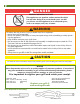
LP Gas Grill Assembly and Use Manual 6212S00T91 6512S0DT91 For Outdoor Household Use Only. Not for Commercial Use. Need Help? Need to Register Your Grill? Looking for Aussie Parts & Accessories? Visit us online at www.AussieGrills.com Or call Aussie Customer Service at 1-800-251-7558 ! WARNING • Failure to follow these intructions could result in fire or explosion which could cause death, serious personal injury, or property damage. • Read and follow instructions carefully before assembly or use.
! DANGE R CARBON MONOXIDE HAZARD This appliance can produce carbon monoxide which has no odor. Using it in an enclosed space can kill you. Never use this appliance in an enclosed space, such as a camper, tent, car, or home. ! WARNING To reduce the risk of serious injury or death from fire or explosion: • Never leave grill unattended • Never use alcohol, prescription or non-prescription drugs while assembling or safely operating this appliance. • Keep children and pets away at all times.
Contents Preparation for Assembly.............................................. 3 Parts Identification Parts Illustration .......................................................... 4 Parts List ..................................................................... 5 Assembly Instructions Step 1 Frame Identification ....................................... 6 Step 2 Shroud to Leg Assembly................................. 7 Step 3 Front Crossbrace Assembly ............................
Parts Illustration - Model 6212S00T91 / 6512S0DT91 NOTE: Some illustrations may vary slightly depending on grill Model, however the names are the same.
Parts List- Model / 6212S00T91 / 6512S0DT91 If you need replacement parts, refer to the Parts Illustrations to find the exact parts you need. If you have any questions or need help, contact Customer Service at 1-800-251-7558 or go to www.aussiegrills.com. Be sure to have the grill model number and serial number printed on the black label, located on the back of the cart shroud. If you need a replacement part under warranty, a proof of purchase will be necessary.
Assembly Instructions Step 1 Frame Identification NOTE: Some illustrations may show parts that are not included in your grill or are a different size. If assembly method is different it will be noted. If not, proceed as instructed. Identify parts and lay on floor as shown. Parts are named for their assembled position on the grill. The two Top UFrames are symmetrical so will work on the left or right.
Step 2 Shroud to Leg Assembly The next 2 steps are best performed on a smooth level surface (and/or with the help of a second person) Place the shroud on Leg Frames as shown. Install a 5/32-30 x .39” bolt through each bottom corner of the shroud and into the threaded insert in the inside face of the legs. Next, insert a 1/4-20 x 1.1” bolt through the front of the right frame, through the shroud and fasten in place with a 1/4-20 nut.
Step 4 Tank Side Brace & Top Crossbrace Assembly A. Place the Tank Side Brace inside the left Top U-Frame, with the open side facing inwards and the threaded inserts at the bottom. Install a 1/4-20 x 1.1” bolt through the front of the U-Frame then through the top corner of the Shroud and into the threaded insert inside the Tank Side Brace. Next, install a 1/4-20 x .39” bolt through the hole in the end of the Tank Side Brace and into the threaded insert in the inside face of the U-Frame. 1/4-20 x 1.
Step 5 Crossbrace & Right Tube Brace Assembly A. Assemble one Crossbrace to the inside of the back legs as shown with the short flange of the Crossbrace to the top and facing inwards. Install 4) 1/4-20 x .39” bolts through the holes in the Crossbrace and into the threaded inserts in the inside face of the legs. B. Install the Right Tube Brace between the right legs and fasten in place with a 1/4-20 x 1.1” bolt through the outside of each leg and into the ends of the Tube Brace. 1/4-20 x .
Step 7 (Model 6212) Wheel Assembly Place the Tank Support between the Left Legs so the holes in the end align with the holes in the legs with the flanges facing up. The flanges have notches with different spacing; the side with the notches closer together should be to the inside of the cart. Insert an Axle through the Wheel, the leg tube and the Tank Support end. Fasten in place by inserting an Axle Pin through the small hole near the end of the Axle.
Step 8 Bowl Support & Hinge Half Assembly A. Attach the Bowl Supports and Flavor Activator Supports to the Bowl, orientated as shown. With the Flavor Activator Support on the inside of the Bowl and the Bowl Support on the outside, attach both Supports to the Bowl using the same pair of 1/4-20 x .59” Bolts, Fiber Washers and Nuts. The bolt and fiber washer are on the inside of the Bowl. Repeat this for the other side. B. Attach the Bowl Hinge Halves to the Bowl, oriented with the open side up.
Step 10 Main Burner Assembly A A. Slide the burner tubes down through the indicated holes in the bowl and align the holes in the burner brackets with the holes in the Bowl. B. From underneath the Bowl, fasten the Main Burner to the Bowl with 2) #5 x .31” Tapping Screws. #5 x .31” Tapping Screw 2 pcs. B Step 10A (6512 ONLY) Tank Heat Shield Attachment Fasten the Tank Heat Shield to the bottom of the Bowl with two 1/2-20 x .39” bolts with fiber washers and two 1/4-20 nuts.
Step 11 Bowl to Cart Assembly Place the Bowl Supports on top of the U-Frames, aligning the holes. Attach the Bowl to the cart with four 1/4-20 x .39” Bolts through the bowl Supports and into inserts in the top of the U-Frames. 1/4-20 x .39” Bolt 4 pcs Step 12 Manifold Assembly (and Piezo Igniter Assembly on Model 6212) NOTE: Regulator hose is shipped attached to the Manifold. (Model 6512 has Ignition Module pre-installed) A.
Step 12C Control Panel Heat Shield - Model 6512 ONLY 5/32-30 x .31” Bolt Tuck top flange of 6512 Control Panel Heat Shield under the top flange of the inside of the Control Panel so that the holes align. Insert two 5/32-30 x .31” Bolts through the holes in both parts and fasten in place with two 5/32-30 Nuts 5/32-30 Nut 5/32-30 x .
Step 14 A. Main Burner Electrode Assembly Insert small end of Electrode Wire down through the hole in the Bowl in front of the main burner until flange of collector box rests on front edge of burner. Fasten Electrode collector box to the burner with 1) #5 x .31” Tapping screw. A Front of Grill Main Burner Electrode #5 x .31” Tapping Screw 1 pc. B.
Step 15 Side Table Assembly Place the Side Table flanges with holes around the outside of the U-Frame and align the holes. Insert a 1/4-20 x 1.2” Stair Screw through each of the four Side Table holes and then through the U-Frame. Fasten each securely with a 1/4-20 Nut. Repeat for other Side Table. (Note: Side Tables are interchangable) 1/4-20 x .1.2” Stair Screw 1/4-20 x .1.
Step 17 Hood Handle Assembly Model 6212: Attach the Hood Handle to the Hood with 2) 1/4-20 x .39” Bolts and Fiber Washers. Place Heat Baffles between the Handle and the Hood, orienting baffles so they align with the end of the handle. Model 6512: Attach the Hood Handle and the Hood Handle Heat Shield to the Hood with 2) 1/4-20 x .39” Bolts. The Heat Shield is placed inside the Hood with the raised areas around the holes against the hood.
! CAUTION To reduce the risk of a laceration hazard: • Wear protective gloves when installing warming rack. Hood and Bowl edges could be sharp. Step 19 Flavor Activator / Warming Rack Assembly A. Place Flavor Activator on Supports in Bowl. B. Install Warming Rack as follows: First insert legs 1 and 2 in holes on right side of Bowl and Hood. Next, while hold- ing leg 3, insert leg 4 into hole in left side of Hood.
! WARNING To reduce the risk of serious bodily injury or death from fire or explosion: Never remove guards or devices to prevent storage of spare or oversize LP Gas Cylinders not recommended for this grill. Step 21 Tank Blocking Wire Assembly Attach the Tank Blocking Wire to the cart as follows. 1) Insert the Z shaped end into the hole in the bottom flange of the control panel inside the cart. 2) Rotate the Wire so that the first leg is resting on the control panel flange.
Step 22 Drip Cup Assembly Insert the Drip Cup into the hanger wire underneath the grill bowl. Step 23 Battery Installation (6512 only) Unscrew Igniter Cover and insert AA Battery with the negative “-“ end going in first. Replace the cover and tighten securely. + - This Completes the Grill Assembly. NOTE: Verify ALL hardware is tightened Securely.
Connecting/Disconnecting the Gas Using Gas ! DANGE R Carbon Monoxide Hazard • This appliance can produce carbon monoxide which has no odor. Using it in an enclosed space can kill you. • Never use this appliance indoors, on recreational vehicles, or boats. ! WARNING To reduce the risk of serious bodily injury or death from fire or explosion: • Use only propane gas with this LP gas grill. • Do not attempt to convert an LP unit to natural gas.
LP Hose and Regulator ! WARNING To reduce the risk of serious bodily injury or death from fire or explosion: • Clean and inspect the gas hose/regulator before each use of the outdoor cooking gas appliance. The gas hose/regulator must be replaced prior to being used, if there is evidence of excessive abrasion or wear, or if the hose is cut or leaks. • Use only the gas hose/regulator assembly that has been supplied with this gas grill. Do not use hose/regulator from another manufacturer.
Before Using Your LP Gas Grill Installation Codes ! WARNING To reduce the risk of serious bodily injury or death from fire or explosion: • This installation must conform with local codes or, in the absence of local codes, with either the National Fuel Gas Code, ANSI Z223.1/NFPA 54 Natural Gas and Propane Installation Code, CSA B149.1, or Propane Storage and Handling Code, B149.2 or the Standard for Recreational Vehicles, ANSI A 119.
How to Perform A Leak Test “FIRST TIME USE” and as required Supplies Needed for a Leak Test: • Clean paint brush • Water • Dish washing liquid 1. Use an LP Gas Cylinder equipped with an OPD (Overfill Prevention Device) and have it filled at an authorized LP gas dealer by a qualified attendant. 2. Make sure all grill Control Panel Knobs are turned to the “Off” position and verify that the LP Gas Cylinder valve is closed by turning the knob on the LP Gas Cylinder clockwise until it stops. 3.
6. If “growing” bubbles appear on any of the connection points, you have detected a gas leak. Immediately close the LP Gas Cylinder valve by turning handle clockwise a. If leak appears at either end of hose and regulator assembly, retighten the connection at the leak, but do not over-tighten. (NOTE: Only hand tighten at coupling nut in Fig. 1 shown on previous page) Repeat Leak Test. b.
Lighting the Grill Using the Ignitor (continued) 1. Open the Hood. 2. IMPORTANT: Make sure Control Knobs are turned “Off.” (Fig. 4) Turn LP Gas Cylinder valve counterclockwise 3. Turn the LP Gas Cylinder valve open counterclockwise until it stops. (Fig. 5) Control Knob in Off position Control Knob in High position (large flame symbol) Fig. 5 Fig. 4 Left Main Burner Control Knob Right Main Burner Control Knob Igniter Button Fig. 6 4.
Manually Lighting the Grill ! WARNING To reduce the risk of serious bodily injury or death from fire or explosion: • Open Hood before lighting the grill to prevent an explosion from gas build-up. 1. Open the Hood. 2. IMPORTANT: Make sure Control Knobs are turned “Off.” (Fig. 4 - P.26) 3. Turn the LP Gas Cylinder valve open counterclockwise until it stops. (Fig. 5- P.26) 4. Locate match-lighting hole at the right end of the Grill Bowl or burner tube hole in bowl bottom.
Cooking On the Gas Grill ! WARNING To reduce the risk of serious bodily injury or death from fire, explosion or burn hazard: • Never use charcoal or lighter fluid in your gas grill. Keep this outdoor cooking appliance clear and free from combustible materials, gasoline, and other flammable vapors and liquids. • Keep any electrical supply cord and regulator hose away from any heated surfaces.
Grill Cooking (Direct Method) Direct Cooking on the Grids: Food is cooked directly over the heat source. The Burners heat up the Flavor Activators under the Cooking Grids, which in turn heat the food on the grill. The natural food juices from cooking fall onto the hot Flavor Activators below and vaporize. Rising smoke bastes the food, giving it that unique barbecued flavor. Use the Direct Cooking method for foods that take less than 25 minutes to cook: steaks, chops, kabobs, sausages, and more.
Warming Rack ! WARNING To reduce the risk of fire or flare-up from grease drippings: • When cooking food on the warming rack, make sure no Burners are on directly under the Drip Pan. • Clean grease drippings away from grill after each use. Warming Racks are a convenient way to cook food, keep cooked food warm or to warm items such as bread or rolls. To keep foods warm, set the Burners on Low or turn off all that are not needed.
Cooking Grid/Flavor Activators: Clean the residue off with a baking soda and water solution. For stubborn stains, use a non-abrasive scouring powder. Do not use steel wool or other abrasive cleaners that can scratch the stainless steel or porcelain-coated surfaces. This can cause foods to stick on the Cooking Grids. All Other Cleaning: For further cleaning, use hot soapy water and a cloth, or nylon-bristled brush only. Do not immerse the Gas Controls or Manifold in water.
6. Check the Gas Collector Box to verify that there is a 3/16” gap between the electrode tip and the top flange of the box as shown in Fig. 12. Fig. 12 3/16” gap Gas Collector Box - If no spark, pinch together or open Gas Collector Box to adjust 3/16” gap between electrode tip and V-notch. NOTE: Before next step, you may wish to clean the rest of the grill. See Grill Cart, Bowl and Hood (p. 30). 7. After cleaning, refit the Burner. NOTE: When refitting the Burner, be sure it is positioned correctly.
Emergencies Problem Possible Cause Solution Gas leaking from cracked/cut/burned hose Damaged hose Turn off gas at the LP Gas Cylinder. Replace valve/hose regulator before continuing use. Gas leaking from LP Gas Cylinder Mechanical failure due to rust or mishandling Replace LP Gas Cylinder. Gas leaking from LP Gas Cylinder valve Failure of valve from mishandling or mechanical malfunction Turn off LP Gas Cylinder valve. Return Cylinder to gas supplier.
Troubleshooting Problem Possible Cause Solution Regulator coupling nut is not fully connected to LP cylinder Tighten coupling nut by hand about one-half to three quarters additional turn. Do not use tools. LP-Excess flow valve tripped in regulator Turn Control Knobs to “Off” position and turn LP Gas Cylinder handle clockwise until it stops. Wait five minutes. Relight LP gas grill. If flame continues to be low, turn off gas at LP Gas Cylinder and grill.
Problem Possible Cause Solution Flare up Grease build-up Clean grill. Excessive fat in meat Trim fat from meat before grilling. Persistent grease fire Grease trapped around burner Turn Control Knobs “Off” and turn handle of LP Gas Cylinder system clockwise until it stops. Open Hood carefully and let fire burn out. After the grill cools, remove and clean all parts.
Limited Warranty MECO CORPORATION - LIMITED WARRANTY This product is warranted to the original consumer purchaser against defects in material and workmanship under normal outdoor household use and correct assembly (if assembled by the consumer purchaser). Burners are warranted for a period of one (1) years from the date of purchase. Stainless steel parts are warranted for a period of one (1) year (for rust-through only) from the date of purchase.