Aussie ® by Meco® LP Gas Grill Assembly and Use Manual Koala TM MODEL 7900 Series Liquid Propane Gas Grill FOR OUTDOOR HOUSEHOLD USE ONLY. NOT FOR COMMERCIAL USE. For Customer Service, call 1-800-251-7558 or visit our web site at www.meco.net • Failure to follow these instructions could result in fire or explosion which could cause death, serious personal injury, or property damage. • Read and follow instructions carefully before assembly or use.
— NOTICE — MECO CORPORATION STRIVES TO BE A QUALITY SUPPLIER OF CONSUMER PRODUCTS. IF WE OMITTED ANY PARTS NEEDED FOR ASSEMBLY, OR YOU NEED TROUBLESHOOTING INFORMATION, PLEASE CONTACT US USING OUR TOLL FREE NUMBER. THANK YOU FOR PURCHASING A MECO CORPORATION PRODUCT. 1-(800)-251-7558 8 am - 6 pm E.S.T Mon. - Fri. 1-(423)-639-1171 (TELEPHONE) 1-(423)-639-2570 (FAX) www.meco.net CONTENTS CONSUMER SERVICE DEPARTMENT MECO CORPORATION 1500 INDUSTRIAL ROAD GREENEVILLE, TN. 37745 USA III.
PARTS ILLUSTRATIONS If you need replacement parts, refer to the Parts Illustrations and the Parts List to find the exact parts you need. If you have any questions which require help, contact Customer Service and be sure to mention the model number of your grill.
(35) Side Burner Grid (36) Bolt, M6x75 2 pc (37) Heat Shield (38) Handle Spacer (41) Cooking Grid (40) Flame Diffuser (42) Warming Rack (43) Fabric Panel (46) Main Burner Electrode (47) Control Panel w/Manifold and Regulator 4 (39) Hood Handle (44) Main Burner (45) LP Cylinder Heat Shield
03.6222.
To reduce the risk of a cut injury: · Wear protective gloves when handling parts that have sharp edges. · Some assembly may require help from another person. Observe where noted. TOOLS: STEP 1) Cart Assembly: or 3 Attach the Legs to the Bottom Shelf with M5 x 35 Bolts threaded into the Bottom Shelf holes. Position legs with the holes exactly as indicated .
STEP 2) Assemble Axle, Wheels & Wheel Covers: (9) with Item (11) installed (10) WHEEL 2 PCS (9) AXLE (11) Nut, M8 2 PCS (12) WHEEL COVER 2 PCS (10) WHEEL (11) Nut, M8 WHEEL LEGS Push Axle through holes in Wheel Legs. Place Wheels on both ends of Axle, then tighten with two M8 Nuts with wrench or pliers. Align Wheel Cover pins with 3-holes in Wheel and snap flush against wheel. (12) WHEEL COVER FIG.
Step 4) Install Drip Cup: Align groove with vertical wire Insert Drip Cup into Drip Cup Holder ring until the cup flange is flush with the ring and the notch in the lip of the cup fits the vertical hanger wire. Step 5) Assemble Sidebraces and Rear Crossbrace: (17) Drip Cup · Attach Right and Left Sidebraces (19 & 20) to legs with ST4.0 x 10 Screws. (FIG. 5A) Secure Bottom Heat Shield to Left Sidebrace with M4x10 Screws and M4 Wingnuts. (FIG. 5B) Allow Heat Shield Edge to overlap Sidebrace edge.
Step 6) Assemble Side Tables: Align bracket holes of Left and Right Side Tables with holes in Bowl Leg Brackets. Attach Side Tables with M6X15 Screws underneath. (26) Right Side Table (27) Left Side Table (28) Screw, M6x15 8 pcs FIG. 6B (28) Screw, M6X15 (28) Screw, M6x15 FIG. 6A Step 7) Assemble Side Burner Valve and Knob: · Align Valve Stem and Bracket holes with holes in Side Table. Attach M4 x 10mm Screws to Valve brackets and tighten. (FIG. 7A) · Push Control Knob onto the valve stem. (FIG.
Step 8) Assemble Side Burner Electrode and Side Burner: · Feed Electrode wire through upper left hole from large center hole in Side Burner Reflector. (FIG. 8A) Allow electrode to follow wire into hole and lie flat. (8B) (32) Side Burner Electrode 1 pc Side Burner Electrode Electrode Wire through hole (33) Side Burner 1 pc (23) Wingnut, M4 1 pc (35) Side Burner Grid 1 pc FIG. 8A FIG. 8B · Insert Side Burner tube through large hole in Side Burner Pan.
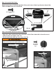
· Align prongs of Side Burner Grid with holes in Side Table and lower grid into the holes. (FIG. 8F) Side Table Assembly Finished (35) Side Burner Grid FIG. 8F FIG. 8G Step 9) Attach Hood Handle and Shield: Open Hood. Insert M6 Bolts through Heat Shield, Hood, through large end of Handle Spacers and to the Handle. Tighten bolts into the Handle inserts. Do not over tighten; the porcelain grill coating may crack.
Step 10) Install Flame Diffuser: Flame Diffuser mounting stud in Bowl. Place the Flame Diffuser over the Main Bowl Burner, onto the two mounting studs on each side of the Bowl. (FIG.10) (40) Flame Diffuser (40) Flame Diffuser FIG. 10 (41) Warming Rack 1 pc 4 (41) Warming Rack (42) Cooking Grid 1 pc 3 Step 11) Install Warming Rack/Cooking Grid: Position Warming Rack as shown. (FIG. 11A) Insert legs 1 and 2 in holes on right side of grill Bowl and Hood respectively.
CONNECTING/DISCONNECTING THE GAS USING GAS CARBON MONOXIDE HAZARD · This appliance can produce carbon monoxide which has no odor. Using it in an enclosed space can kill you. · Never use this appliance indoors, on recreational vehicles, or boats. To reduce the risk of serious bodily injury or death: · Use only propane gas in this LP gas grill. · Do not attempt to convert an LP unit to natural gas. · Any use or alteration of this unit not intended could be unsafe and will void your warranty.
3) Lift and swing LP Cylinder Retainer Clip to outside of grill. Set LP cylinder in the large hole inside the Bottom Shelf. Rotate the LP cylinder toward the front of grill so regulator hose may connect. (FIG. 13A) Make sure hose is routed outside and under crossbrace. Rotate Cylinder Cylinder Retainer Clip Hand tighten coupling nut in clockwise direction FIG. 13A Remove 4) Swing the Cylinder Retainer Clip over round Protective Cap FIG. 13C shoulder of the LP cylinder.
6) Check for leaks by brushing the soap solution on all gas valves, hose connections and fittings. (shown by the heavy arrows in (FIG. 14A, 14B & 14C) Make sure you generously brush the locations with the soap solution, completely surrounding the connections and fittings. 7) If “growing” bubbles appear on any of the connection points, you have detected a gas leak. Immediately close the LP cylinder valve by turning handle clockwise.
FIG. 14C Control Knob in OFF position FIG.15A Side Burner fittings under Side Table LIGHTING THE GRILL USING THE IGNITOR To reduce the risk of serious bodily injury or death: · Open Hood before lighting the grill to prevent an explosion from any gas accumulation. · If lighting attempts fail, or the burners go out during operation, turn all control knobs “Off” to dissipate any accumulation of gas. Accidental ignition could occur. Wait five minutes before repeating lighting procedure.
MANUAL LIGHTING THE GRILL To reduce the risk of serious bodily injury or death: · Open Hood before lighting the grill to prevent an explosion from any gas accumulation. · If lighting attempts fail, or the burners go out during operation, turn all control knobs “Off” to dissipate any accumulation of gas. Accidental ignition could occur. Wait five minutes before repeating lighting procedure. · Light both left and right sides of burner to prevent gas from accumulating.
MANUAL LIGHTING THE SIDE BURNER Cooking on the Grids: The burners heat up the Flame Diffusers under the Cooking Grids, which in turn heat the food on the grill. The natural food juices from cooking fall onto the hot Flame Diffusers below and vaporize. Rising smoke bastes the food, giving it that unique barbecued flavor. To reduce the risk of serious bodily injury or death: · If lighting attempts fail, or the burner goes out during operation, turn control knob “Off” to dissipate any accumulation of gas.
· Do not use the grill without the Drip Cup in place. Empty excess grease to avoid a fire under the grill. · If you notice grease or other hot material dripping from the grill onto the valve, hose, or regulator, turn off the gas supply immediately. After the grill has cooled, determine the cause and correct it. After cleaning the valve and hose and regulator assembly, perform a leak test before continuing use. (See Performing a Leak Test.
5) Use a pipe cleaner to clear insect nests from the inlet hole of main burner (FIG. 20C) and side burner ventilation hole. (FIG. 20D) Open up the main burner holes and the side burner holes with a small nail or wire.Normal wear and corrosion may enlarge some holes, however, if large cracks or holes are found, replace the Burner. Use a brass wire brush to remove food particles and corrosion from the burner surfaces. (Note: It is normal for surface rust to be present on the burners.
STORAGE 1) Disconnect LP gas cylinder from grill and store outside, in a dry, well-ventilated area, away from any sources of heat or ignition. Re-cap LP cylinder valve with the Safety Cap. 2) Remove Burners and wrap with aluminum foil to prevent insects from entering the burner holes. Store wrapped Burners on top of cooking grid. 3) You may wrap the Cooking Grid and Flame Diffuser in aluminum foil and place inside the Hood or store inside your dwelling.
Problem: TROUBLESHOOTING (Cont’d) Burner will not light using a match Possible Cause: Solution: LP gas cylinder is empty Take LP gas cylinder to licensed LP gas supplier to be refilled. LP Coupling nut is not fully connected to regulator Tighten coupling nut by hand about one-half to three quarters additional turn. Do not use tools. Burner is not connected to Valve.
IMPORTANT NOTICE This Gas Grill must be used with a LP Gas Cylinder equipped with an OPD (Overfill Prevention Device). This is a secondary device to prevent the overfill of your LP Gas cylinder. The proper methods for the filling of your LP Gas cylinder are by weight or volume, as described in NFPA 58. Please make sure your filling station fills your LP Gas cylinder by weight or volume. Ask your filling station to read purging and filling instructions on the LP cylinder before attempting to fill.
MECO CORPORATION LIMITED WARRANTY This product is warranted to the original consumer purchaser against defects in material and workmanship under normal outdoor household use and correct assembly (if assembled by the consumer-purchaser). Burner and Cooking Grid are warranted for a period of one (1) year from the date of purchase. All other parts are warranted for a period of one (1) year from the date of purchase. Meco Corporation requires proof of purchase and we suggest you keep your receipt.