
Instruction manual

37
Media Servers
Avaya S8300 Media Server and an Avaya G700 Media Gateway
May 2003
• An Avaya P330 processor complex is based on the Avaya P330 data switch architecture.
This complex provides an eight-port Layer 2 switch function and manages the Expansion
and Cascade modules.
• The electrical and physical connectivity for the four Media Module slots.
NOTE:
The Motherboard can not be replaced in the field.
For more information about the VoIP Media Module, see "Avaya MM760 VoIP Media Module"
(page 201).
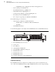
Fans
The G700 Media Gateway contains four 12-volt fans. These fans are monitored and can be
alarmed via SNMP to a management station.
LEDs
The S8300 Media Server with the G700Media Gateway uses two types of LEDs:
• Media Module
• System-level
Media Module LEDs
Media Module LEDs have the following characteristics:
• Each Media Module has at least three LEDs to indicate module and port status or
maintenance and administration modes.
• The location, spacing, and labeling is fixed for all LEDs on every Media Module.
• The LEDs are mounted on the Media Module printed wiring board, and placed so that
they show through an opening.
System-Level LEDs
The LED board provides visual indication of system status and data port status, and allows the
customer to change between status indication modes. The System Level-LEDs have the
following characteristics:
• An LED board is located in the upper left front of each G700 Media Gateway. The front
of the LED board displays the LEDs in an oblong fascia panel.
• The LED board provides visual indication of system and Ethernet port status and allow
the customer to switch between status indication modes.
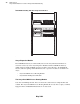
You must remove the LED board when you install or remove the S8300 Media Server or the
S8300 Media Server when used as a LSP. The S8300 Media Server and the LED board must be
installed or removed as a unit.