
Hardware manual
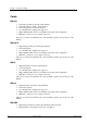
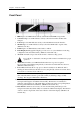
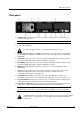


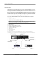
Table Of Contents
- Cover Page
- Contents
- About this guide
- Safety Instructions and safety warnings
- Before you start
- Introduction to NION
- Setting up the NION
- Introduction
- Configuration
- Updating the firmware
- Using the front panel
- Using the web interface
- Using XDAB clusters with VLANs and CobraNet
- Introduction
- Important concepts
- Use cases
- Scenario 1 - Basic network
- Scenario 2 - Network using VLAN
- Scenario 3 - Network with VLAN and analog interconnects
- Scenario 4 - Network with VLAN and digital interconnects
- Scenario 5 - Network with an XDAB cluster
- Scenario 6 - Network with VLAN and XDAB
- Scenario 7 - Network with VLAN and XDAB
- Scenario 8 - Network with VLAN and two XDAB clusters
- Scenario 9 - Network with VLAN and three XDAB clusters
- Setting conductor and XDAB priority in NWare
- Further examples
- Troubleshooting
- Connector ports
- Technical specifications
- Reference Information
- Warranty statement

NION Hardware Manual
May 17, 2011 Version 1.6.2a.0 23
Rear panel
1. Serial Port Female DB-9 panel connector, which provides RS-232 communications for
external control protocols.
Note: On earlier units, this connector is on the front panel.
2. Power Receptacle Flush-mount IEC power receptacle for connecting a compatible IEC
power cable (included).
Use only the supplied cable or an equivalent international version.
3. Module Bays Housing bays for NION series expansion cards. Up to 4 Nio series I/O cards
can be installed in a NION n3 or NION n6. Up to 2 Nio series I/O cards can be installed in
a NION nX.
4. XDAB In RJ-45 panel connector accepts a shielded CAT6 data cable for transport of the
proprietary NION digital audio input bus. (NION n3, n6 only.)
5. XDAB Out RJ-45 panel connector accepts a shielded CAT6 data cable for transport of the
proprietary NION digital audio output bus. (NION n3, n6 only.)
6. GPIO Female DB-25 panel connector provides access to the internal GPIO control
functionality.
7. LAN RJ-45 panel connector accepts a CAT5 data cable for data transport to/from the
internal network interface. This connection is required on all units for system
configuration and inter-unit communications.
8. RS-485/422 Female DB-9 panel connector accepts a standard DB-9 connector (not
included) to provide access to the external RS-485 or RS-422 external control protocols.
9. CobraNet Primary RJ-45 panel connector accepts a CAT5 data cable for data transport
to/from the integrated CobraNet audio transport network interface.
10. CobraNet Secondary RJ-45 panel connector accepts a CAT5 data cable for data transport
to/from the secondary integrated CobraNet audio transport network interface.
Note: This port does not provide additional CobraNet capacity and only becomes active in
the event that the network connected to the Primary CobraNet port becomes inoperative.
11. Power Supply Industrial ATX format power supply with exhaust fan.
Additional air flow is provided on the side panel opposite the power supply. Install
with at least 2” of free clearance on sides of unit. Do not block any air intake or
exhaust vent.