
Hardware manual
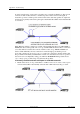
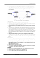
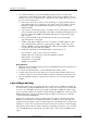
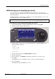

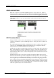
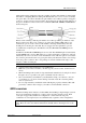
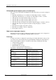
Table Of Contents
- Cover Page
- Contents
- About this guide
- Safety Instructions and safety warnings
- Before you start
- Introduction to NION
- Setting up the NION
- Introduction
- Configuration
- Updating the firmware
- Using the front panel
- Using the web interface
- Using XDAB clusters with VLANs and CobraNet
- Introduction
- Important concepts
- Use cases
- Scenario 1 - Basic network
- Scenario 2 - Network using VLAN
- Scenario 3 - Network with VLAN and analog interconnects
- Scenario 4 - Network with VLAN and digital interconnects
- Scenario 5 - Network with an XDAB cluster
- Scenario 6 - Network with VLAN and XDAB
- Scenario 7 - Network with VLAN and XDAB
- Scenario 8 - Network with VLAN and two XDAB clusters
- Scenario 9 - Network with VLAN and three XDAB clusters
- Setting conductor and XDAB priority in NWare
- Further examples
- Troubleshooting
- Connector ports
- Technical specifications
- Reference Information
- Warranty statement

Appendix B - Connector ports
76 Version 1.6.2a.0 May 17, 2011
Configurable general purpose ports (16 control pins)
These ports represent the bulk of the GPIO functionality. Each of these ports can be configured
as follows:
Digital In (3.0V TTL logic - Low: 0 VDC - 0.8 VDC; High: 2.0 VDC - 24 VDC)
Digital Out (3.0V TTL logic - Low: 0V DC - 0.4 VDC; High: 2.4 VDC - 3.3 VDC)
Analog In 1K, 12V (using external 12 VDC power source)
Analog In 10K, 12V (using external 12 VDC power source)
Analog In 10K, 24V (using external 24 VDC power source)
Analog In 1K, self powered (pin feeds required voltage through pot or switch to common)
Analog In 10K, self powered (pin feeds required voltage through pot or switch to
common)
Rotary Encoder (requires 2 pins and a common)
Raw (all modes available, software configurable)
Clock signals on pins 6-8.
High current output ports (4 ports)
Each high current port provides 11.5VDC at 0.5A. High current outputs can be configured for
straight logic (on/off) or PWM (Pulse Width Modulation) operation.
Fault relay
A single system relay is configured for supervising project faults. This Form C relay provides
1A contacts and is activated when the front panel fault LED is illuminated, which indicates a
muted condition. Muted conditions could indicate many things, including the following:
A firmware/Role mismatch
A voltage rail malfunction
XDAB Fault Policy exceeded
Network or Network Synchronization lost.
The behavior of the fault relay is summarized below.
Event Fault relay action taken
Role running Pin 25 is connected to pin 12
Role stopped Pin 25 is connected to pin 13
Unit or system muted Pin 25 is connected to pin 13
Project halted Pin 25 is connected to pin 13
Project erased / no project loaded Pin 25 is connected to pin 13
Power off Pin 25 is connected to pin 13