CHAPTER 1 INTRODUCTION Chapter 1 INTRODUCTION The MICRO ATX ZX mainboard is a high-performance personal computer mainboard based on the Intel® Pentium® II/Pentium® III/CeleronTM processor. This mainboard combines leading edge nVIDIA Riva TNT2 M64 technology in graphics and Creative® ES1373 PCI technology in audio. The Intel® Pentium® II/III/CeleronTM processor supports MMXTM (Multimedia Extension) technology.
CHAPTER 1 INTRODUCTION 1.1 Mainboard Features CPU l Slot 1 for Intel® Pentium® II/Pentium® III/CeleronTM processor. l Supports 233MHz, 266MHz, 300MHz, 333MHz, 350MHz, 400MHz, 450MHz, 500MHz and faster. Chipset l Intel® 440ZX AGPset - support 66 or 100Mhz Host bus frequency - support AGP & PCI l Intel® PIIX4E chipset - PCI to ISA Bridge PC98 Compliant - UltraDMA-33 Master Mode PCI IDE Controller - Super I/O Interface - 324 pin BGA package FSB (Front Side Bus) 66.6MHz and 100MHz clocks are supported.
CHAPTER 1 INTRODUCTION On-Board Peripherals l On-Board Peripherals include: - 1 floppy port supports 2 FDD with 360K, 720K, 1.2M, 1.44M and 2.88Mbytes. - 1 serial port (COM A) + 1 serial connector (COM B) - 1 parallel port supports SPP/EPP/ECP mode - 1 MIDI/Game Port - 2 USB ports - 1 IrDA connector for SIR/FIR. - 1 Audio port (Line_In, Line_Out, and Mic_In Jack) - 1 VGA port VGA l nVIDIA Riva TNT2 M64 - Running on AGP BUS. - Onboard 32MB (4*16M) SDRAM. - 3D Acceleration.
CHAPTER 1 INTRODUCTION Mounting l 6 mounting holes. System Hardware Monitor (optional) l CPU/Power Supply/Chassis Fan Revolution Detect l CPU Fan Control (the fan will automatically stop when the system enters suspend mode) l System Voltage Detect l CPU Overheat Warning.
CHAPTER 1 INTRODUCTION 1.
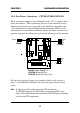
CHAPTER 2 HARDWARE INSTALLATION Chapter 2 HARDWARE INSTALLATION 2.1 Central Processing Unit: CPU 2.1-1 Processor Installation Procedures Step 1: Install the Retention Mechanism. Attach the Retention Mechanism to the Mainboard. Push the Plastic lock to secure the Retention Mechanism into the mainboard.
CHAPTER 2 HARDWARE INSTALLATION 2.1-2 CPU Core Speed Derivation Procedure 1. The DIP Switch SW1 (1, 2, 3, and 4) is used to set the Core/Bus (Fraction) ratio of the CPU. The actual core speed of the CPU is the Host Clock Frequency multiplied by the Core/Bus ratio. For example: If then CPU Clock Core/Bus ratio CPU core speed = = = = = 66MHz/100MHz 4 Host Clock x Core/Bus ratio 66MHz x 4/100MHz x 4 266MHz/400MHz SW1 CPU 1 2 3 4 Core/Bus Ratio ON OFF ON ON 2.
CHAPTER 2 HARDWARE INSTALLATION 2.1-3 CPU Speed Setting: SW1 To adjust the speed of the CPU, you must know the specification of your CPU (always ask the vendor for CPU specification). The mainboard can auto-detect between 66 or 100MHz CPU Bus Frequency.
CHAPTER 2 HARDWARE INSTALLATION a. 66MHz CPU Bus Frequency CPU Type SW1 4 3 2 1 4 3 2 1 4 3 2 1 4 3 2 1 233MHz 266MHz 300MHz 333MHz Table 2.1 233 ~ 333MHz Intel® Pentium® II/III/CeleronTM processor b. 100MHz CPU Bus Frequency CPU Type SW1 4 3 2 1 4 3 2 1 4 3 2 1 4 3 2 1 4 3 2 1 350MHz 400MHz 450MHz 500MHz 550MHz Table 2.
CHAPTER 2 HARDWARE INSTALLATION 2.1-4 Fan Power Connectors: CPUFAN/PSFAN/SYSFAN These connectors support system cooling fan with + 12V. It supports three pin head connector. When connecting the wire to the connector, always take note that the red wire is the positive and should be connected to the +12V, the black wire is Ground and should be connected to GND.
CHAPTER 2 HARDWARE INSTALLATION 2.2 Clear CMOS Jumper: JBAT1 A battery must be used to retain the mainboard configuration in CMOS RAM. Short 1-2 pins of JBAT1 to store the CMOS data. 1 3 JBAT1 1 1 2 2 3 3 Clear Data Keep Data Note: You can clear CMOS by shorting 2-3 pin, while the system is off. Then, return to 1-2 pin position. Avoid clearing the CMOS while the system is on, it will damage the mainboard. Always unplug the power cord from the wall socket.
CHAPTER 2 HARDWARE INSTALLATION 2.3 Memory Installation 2.3-1 Memory Bank Configuration ! WARNING! DIMM2(Bank2+ Bank3) DIMM1(Bank0 + Bank1) The mainboard supports a maximum memory size of 256MB (8M x 8) for SDRAM: It provides two 168-pin unbuffered DIMMs (Double In-Line Memory Module) sockets. It supports 8 MB to 256 Mbytes DIMM memory module. There are two kinds of DIMM specification supported by this mainboard: PC100 and PC66. If you use 66MHz CPU Bus Frequency, these two DIMM Specs. is supported.
CHAPTER 2 HARDWARE INSTALLATION 2.3-2 Memory Installation Procedures A. How to install a DIMM Module Single Sided DIMM Double Sided DIMM 1. The DIMM slot has a two Notch Key “VOLT and DRAM”, so the DIMM memory module can only fit in one direction. 2. Insert the DIMM memory module vertically into the DIMM slot. Then push it in. DRAM VOLT 3. The plastic clip at the side of the DIMM slot will automatically close.
CHAPTER 2 HARDWARE INSTALLATION 2.3-3 Memory Population Rules 1. Supports only SDRAM DIMM. 2. To operate properly, at least one 168-pin DIMM module must be installed. 3. This mainboard supports Table Free memory, so memory can be installed on DIMM1 or DIMM 2 in any order. 4. Supports 3.3 volt DIMM. 5. The DRAM addressing and the size supported by the mainboard is shown below: Table 2.3-1 SDRAM Memory Addressing DRAM Tech.
CHAPTER 2 HARDWARE INSTALLATION 2.4 Case Connector: JFP The Power Switch, Reset Switch, Power LED, Speaker, Keylock and HDD LED are all connected to the JFP connector block.
CHAPTER 2 HARDWARE INSTALLATION 2.4-1 Power Switch Connect to a 2-pin push button switch. This switch has the same feature with JRMS1. 2.4-2 Reset Switch Reset switch is used to reboot the system rather than turning the power ON/ OFF. Avoid rebooting while the HDD LED is lit. You can connect the Reset switch from the system case to this pin. 2.4-3 Power LED The Power LED is lit while the system power is on. Connect the Power LED from the system case to this pin.
CHAPTER 2 HARDWARE INSTALLATION 2.5 Floppy Disk Connector: FDD The mainboard also provides a standard floppy disk connector that supports 360K, 720K, 1.2M, 1.44M and 2.88M floppy disk types. This connector supports the provided floppy drive ribbon cables.
CHAPTER 2 HARDWARE INSTALLATION 2.6 Hard Disk Connectors: IDE1 & IDE2 Primary IDE Connector Secondary IDE Connector The mainboard has a 32-bit Enhanced PCI IDE Controller that provides PIO mode 0~4, Bus Master, and Ultra DMA/33 function. It has two HDD connectors IDE1 (primary) and IDE2 (secondary). You can connect up to four hard disk drives, CD-ROM, 120MB Floppy (reserved for future BIOS) and other devices to IDE1 and IDE2. These connectors support the provided IDE hard disk cable.
CHAPTER 2 HARDWARE INSTALLATION 2.7 Power Supply 2.7-1 ATX 20-pin Power Connector: JWR1 This connector supports the power button on-board. Using the ATX power supply, functions such as Modem Ring Wake-Up and Soft Power Off are supported by this mainboard. This power connector supports instant power on function which means that system will boot up instantly when the power connector is inserted on the board. 11 1 20 10 ATX Power Connector PIN DEFINITION PIN SIGNAL PIN SIGNAL 11 3.3V 1 3.3V 12 -12V 2 3.
CHAPTER 2 HARDWARE INSTALLATION 2.7-2 Remote Power On/Off Switch: JRMS1 Connect to a 2-pin push button switch. During OFF state, press once and the system turns on. During ON stage, push once and the system goes to sleep mode: pushing it more than 4 seconds will change its status from ON to OFF. If you want to change the setup, you could go to the BIOS Power Management Setup. This is only used for ATX type power supply.
CHAPTER 2 HARDWARE INSTALLATION 2.8 IrDA Infrared Module Connector: IR The mainboard provides one 5-pin infrared (IR) connector for IR modules. This connector is for optional wireless transmitting and receiving infrared module. You must configure the setting through the BIOS setup to use the IR function. FIR and Consumer IR are reserved functions.
CHAPTER 2 HARDWARE INSTALLATION 2.9 Serial Port Connectors: COM 1 and COM 2 The mainboard has a 9-pin male DIN connector for serial port COM 1. This port is a 16550A high speed communication port that send/receive 16 bytes FIFOs. You can attach a mouse or a modem cable directly into this connector.
CHAPTER 2 HARDWARE INSTALLATION 2.10 Parallel Port Connector: LPT The mainboard provides a 25 pin female centronic connector for LPT. A parallel port is a standard printer port that also supports Enhanced Parallel Port(EPP) and Extended capabilities Parallel Port(ECP).
CHAPTER 2 HARDWARE INSTALLATION 2.11 Mouse Connector: JKBMS1 The mainboard provides a standard PS/2® mouse mini DIN connector for attaching a PS/2® mouse. You can plug a PS/2® mouse directly into this connector. The connector location and pin definition are shown below: Pin6 NC Pin5 Mouse Clock Pin3 GND Pin4 VCC Pin1 Mouse DATA Pin2 NC PS/2 Mouse (6-pin Female) 2.12 Keyboard Connector: JKBMS1 The mainboard provides a standard PS/2® keyboard mini DIN connector for attaching a keyboard.
CHAPTER 2 HARDWARE INSTALLATION 2.13 Joystick/Midi Connectors You can connect joystick or game pads to this connector. Joystick/MIDI 2.14 Audio Port Connectors Line Out is a connector for Speakers or Headphones. Line In is used for external CD player, Tape layer, or other audio devices. Mic is a connector for the microphones.
CHAPTER 2 HARDWARE INSTALLATION 2.15 USB Connectors The mainboard provides a UHCI(Universal Host Controller Interface) Universal Serial Bus root for attaching USB devices like: keyboard, mouse and other USB devices. You can plug the USB device directly to this connector.
CHAPTER 2 HARDWARE INSTALLATION 2.16 VGA DB 15 Pin Connector The mainboard provides a DB 15-pin connector to connect to a VGA monitor.
CHAPTER 2 2.17 HARDWARE INSTALLATION Power Saving Switch Connector: JGS1 Attach a power saving switch to JGS1. When the switch is pressed, the system immediately goes into suspend mode. Press any key and the system wakes up.
CHAPTER 2 HARDWARE INSTALLATION 2.18 Power Saving LED Connector: JGL1 JGL1 can be connected with two-color LED. There are two types of LED that you can use: 3-pin LED or 2-pin LED(ACPI request). When the 2-pin LED is connected to JGL1: the light will turn color green, when system is On; during sleep mode, the 2-pin LED will change color from Green to Orange. For 3-pin LED, when LED is connected to JGL1 this will light when the system is On and blinks when it is in suspend/sleep mode.
CHAPTER 2 HARDWARE INSTALLATION 2.19 Wake-Up on LAN Connector: JWOL The JWOL connector is for use with LAN add-on cards that supports Wake Up on LAN function. To use this function, you need to set the “Wake-Up on LAN” to enable at the BIOS Power Management Setup. 1 3 JWOL PIN 1 2 3 SIGNAL 5VSB GND MP_WAKEUP Note: LAN wake-up signal is active “high”. Note: To be able to use this function, you need a power supply that provide enough power for this feature.
CHAPTER 2 HARDWARE INSTALLATION 2.20 Modem Wake Up Connector: JMDM1 The JMDM1 connector is for used with Modem add-on card that supports the Modem Wake Up function. To use this function, you need to set the “Power On by Ring” to enable at the BIOS Power Management Setup. 5 1 JMDM1 PIN 1 2 3 4 5 SIGNAL NC GND MDM_WAKEUP NC 5VSB Note: Modem wake-up signal is active “low”. Note: To be able to use this function, you need a power supply that provide enough power for this feature.
CHAPTER 2 HARDWARE INSTALLATION 2.21 Modem-In: J5 The connector is for Modem with internal voice connector. SPK IN GND MIC OUT J5 SPK_IN is connected to the Modem Speaker Out connector. MIC_OUT is connected to the Modem Microphone In connector.
CHAPTER 2 HARDWARE INSTALLATION 2.22 AUX Line In Connector: J7 This connector is used for DVD Add on Card with Line In connector.
CHAPTER 2 HARDWARE INSTALLATION 2.23 CD-In Modem Connector: J8 This connector is for Modem with internal voice connector.
CHAPTER 2 HARDWARE INSTALLATION 2.24 Keyboard Power: JVSB1 The JVSB1 jumper is for setting keyboard power. This function is provided by keyboard and PS/2 mouse Wake-up function which can be set through BIOS. 1 3 JVSB1 1 1 3 3 5V Standby (default) Enable keyboard power on function 5V Disable keyboard power on function Note: To be able to use this function, you need a power supply that provide enough power for this feature.
CHAPTER 3 AWARD® BIOS SETUP Chapter 3 AWARD® BIOS SETUP Award® BIOS ROM has a built-in Setup program that allows users to modify the basic system configuration. This type of information is stored in battery-backed RAM (CMOS RAM), so that it retains the Setup information when the power is turned off.
CHAPTER 3 AWARD® BIOS SETUP 3.1 Entering Setup Power on the computer and press immediately to allow you to enter Setup. The other way to enter Setup is to power on the computer. When the below message appears briefly at the bottom of the screen during the POST (Power On Self Test), press key or simultaneously press , , and keys.
CHAPTER 3 AWARD® BIOS SETUP 3.3 The Main Menu Once you enter Award® BIOS CMOS Setup Utility, the Main Menu (Figure 1) will appear on the screen. The Main Menu allows you to select from ten setup functions and two exit choices. Use arrow keys to select among the items and press to accept or enter the sub-menu. ROM PCI/ISA BIOS (2A69KM4J) CMOS SETUP UTILITY AWARD SOFTWARE, INC.
CHAPTER 3 AWARD® BIOS SETUP Chipset Features Setup This setup page includes all the items of chipset special features. Power Management Setup This category determines the power consumption for system after setting the specified items. Default value is Disable. PNP/PCI Configuration Setup This category specifies the IRQ level for PCI and ISA devices. Load Setup Defaults Chipset defaults indicates the values required by the system for the maximum performance.
CHAPTER 3 AWARD® BIOS SETUP 3.4 Standard CMOS Setup The items in Standard CMOS Setup Menu are divided into 10 categories. Each category includes no, one or more than one setup items. Use the arrow keys to highlight the item and then use the or keys to select the value you want in each item. ROM PCI/ISA BIOS (2A69KM4J) STANDARD CMOS SETUP AWARD SOFTWARE, INC.
CHAPTER 3 AWARD® BIOS SETUP Date The date format is . Day month date year Day of the week, from Sun to Sat, determined by BIOS. Read-only. The month from Jan. through Dec. The date from 1 to 31 can be keyed by numeric function keys. The year, depends on the year of the BIOS Time The time format is . PrimaryMaster/PrimarySlave SecondaryMaster/Secondary Slave These categories identify the types of 2 channels that have been installed in the computer.
CHAPTER 3 AWARD® BIOS SETUP If the controller of HDD interface is ESDI, the selection shall be “Type 1”. If the controller of HDD interface is SCSI, the selection shall be “None”. If the controller of HDD interface is CD-ROM, the selection shall be “None”. CYLS.
CHAPTER 3 AWARD® BIOS SETUP 3.5 BIOS Features Setup ROM PCI/ISA BIOS (2A69KM4J) BIOS FEATURES SETUP AWARD SOFTWARE, INC.
CHAPTER 3 AWARD® BIOS SETUP CPU Internal Cache The default value is Enabled. Enabled (default) Enable cache Disabled Disable cache Note: The internal cache is built in the processor. External Cache Choose Enabled or Disabled. This option enables the level 2 cache memory. CPU L2 Cache ECC Checking Choose Enabled or Disabled. This option enables the level 2 cache memory ECC(error check correction). Using 66MHz CPU BUS Pentium II processor, set to Enabled or Disabled.
CHAPTER 3 AWARD® BIOS SETUP Boot From LAN First During Enabled, if there’s a LAN card onboard, the priority booting will be from the LAN. Boot Sequence This category determines which drive the computer searches first for the disk operating system (i.e., DOS). The settings are CD-ROM,A,C/ A,C,SCSI/C,A,SCSI/C,CD-ROM,A/CD-ROM,C,A/D,A,SCSI/E,A,SCSI/ F,A,SCSI/SCSI,A,C/SCSI,C,A/C only/LS/ZIP,C. Default value is CDROM,A,C. Swap Floppy Drive Switches the floppy disk drives between being designated as A and B.
CHAPTER 3 AWARD® BIOS SETUP Security Option This category allows you to limit access to the system and Setup, or just to Setup. System The system will not boot and access to Setup will be denied if the correct password is not entered at the prompt. Setup(default) The system will boot, but access to Setup will be denied if the correct password is not entered at the prompt. PCI VGA Palette Snooping Choose Disabled or Enabled.
CHAPTER 3 AWARD® BIOS SETUP Video BIOS Shadow Determines whether video BIOS will be copied to RAM for faster execution. Video shadow will increase the video performance. Enabled (default) Disabled Video shadow is enabled Video shadow is disabled C8000 - CFFFF Shadow/E8000 - EFFFF Shadow Determines whether the optional ROM will be copied to RAM for faster execution.
CHAPTER 3 AWARD® BIOS SETUP 3.6 Chipset Features Setup The Chipset Features Setup option is used to change the values of the chipset registers. These registers control most of the system options in the computer. Choose the “CHIPSET FEATURES SETUP” from the Main Menu and the following screen will appear.
CHAPTER 3 AWARD® BIOS SETUP SDRAM Configuration by Choose SPD, the SDRAM time will load from the DIMM EEPROM value. Choose manual, the value will be set by SDRAM Ras-to-CAS Delay and SDRAM CAS Latency Time. The settings are SPD and Manual. If the DIMM is without EEPROM, then set this item to Manual. Set SDRAM Ras-to-CAS Delay and SDRAM CAS Latency Time to 3. SDRAM RAS to CAS Delay You can select the SDRAM RAS to CAS delay time in HCLKs of 2 or 3 (default).
CHAPTER 3 AWARD® BIOS SETUP Video BIOS Cacheable Select Enabled allows caching of the system BIOS ROM at C0000hF7FFFh, resulting in better video performance. However, if any program writes to this memory area, a system error may result. Enabled Video BIOS access cached Disabled Video BIOS access not cached Video RAM Cacheable Select Enabled allows caching of the video RAM, resulting in better system performance. However, if any program writes to this memory area, a system error may result.
CHAPTER 3 AWARD® BIOS SETUP Passive Release When Enabled, CPU to PCI bus accesses are allowed during passive release. Otherwise, the arbiter only accepts another PCI master access to local DRAM. The settings are Enabled or Disabled. Delayed Transaction The chipset has an embedded 32-bit posted write buffer to support delay transactions cycles. Select Enabled to support compliance with PCI specification version 2.1. The settings are Enabled or Disabled.
CHAPTER 3 AWARD® BIOS SETUP 3.7 Power Management Setup The Power Management Setup will appear on your screen like this: ROM PCI/ISA BIOS (2A69KM4J) POWER MANAGEMENT SETUP AWARD SOFTWARE, INC.
CHAPTER 3 AWARD® BIOS SETUP Power Management User Define Min Saving Max Saving Users can configure their own power management. Pre-defined timer values are used such that all timers are in their MAX value. Pre-defined timer values are used such that all timers are in their MIN value. PM Control by APM No Yes System BIOS will ignore APM when power managing the system. System BIOS will wait for APM’s prompt before it enter any PM mode Note :Enable this for O.S.
CHAPTER 3 AWARD® BIOS SETUP Video Off After The settings are N/A, Standby, Doze, or Suspend. This option is for choosing the setting in which the monitor will turn off. N/A Always turn on. Doze During Doze mode, the monitor will be turned off. Standby During Standby mode, the monitor will be turned off. Suspend During Suspend mode, the monitor will be turned off. The default setting is Standby. MODEM Use IRQ Name the interrrupt request (IRQ) line assigned to the modem (if any) on your system.
CHAPTER 3 AWARD® BIOS SETUP Standby Mode Disable System will never enter STANDBY mode. 1 Min/2 Min/ 4 Min/8 Min/ 20 Min/30 Min/ 40 Min/1 Hr Defines the continuous idle time before the system enters STANDBY mode. If any item defined in the options of “Power Down and Resume events” is enabled & active, STANDBY timer will be reloaded. When the system has entered Standby mode , any of the items that are enabled in “Wake Up Events of Doze and Standby” will trigger the system to wake up.
CHAPTER 3 AWARD® BIOS SETUP Throttle Duty Cycle This option will determine how much power will be used by the CPU , if the system goes into suspend mode. PCI/VGA Act-Monitor During Enabled, if there’s no activity in the monitor screen, the system will go into Power Saving Mode. During Disabled, the system will go into Power Saving Mode, whether there is activity in the monitor screen or not. The settings are Disabled and Enabled. Soft-Off by PWR-BTTN The settings are Delay 4 sec or Instant-off.
CHAPTER 3 AWARD® BIOS SETUP Power on by Alarm This function is for setting date and time for your computer to boot up. During Disabled, you cannot use this function. During Enabled, choose the Date and Time Alarm: Date(of month) Alarm You can choose which month the system will boot up. Set to 0, to boot every month. Time(hh:mm:ss) Alarm You can choose what hour, minute and second the system will boot up.
CHAPTER 3 AWARD® BIOS SETUP Reload Global Timer Events IRQ[3-7,9-15], NMI Primary IDE 0 Primary IDE 1 Secondary IDE 0 Secondary IDE 1 Floppy Disk Serial Port Parallel Port : Enabled : Enabled : Disabled : Disabled : Disabled : Enabled : Enabled : Enabled During Enabled, if any interrupt event occurs, the system will wakeup from suspend mode. During Disabled, the system will not monitor any interrupt event.
CHAPTER 3 AWARD® BIOS SETUP 3.8 PNP/PCI Configuration Setup You can manually configure the PCI Device’s IRQ. The following pages tell you the options of each item & describe the meanings of each options. ROM PCI/ISA BIOS (2A69KM4J) PNP/PCI CONFIGURATION SETUP AWARD SOFTWARE, INC.
CHAPTER 3 AWARD® BIOS SETUP Resources Controlled By By Choosing “Auto”, the system BIOS will detect the system resource and automatically assign the relative IRQ and DMA Channel for each peripheral. By Choosing “Manual”(default), the user will need to assign IRQ & DMA for add-on cards. Be sure that there is no conflict for IRQ/DMA and I/O ports. Note: When choosing “Auto”, you must be sure that all of the system add-on cards are PnP type.
CHAPTER 3 IRQ-15 assigned to DMA-0 assigned to DMA-1 assigned to DMA-3 assigned to DMA-5 assigned to DMA-6 assigned to DMA-7 assigned to AWARD® BIOS SETUP : : : : : : : PCI/ISA PCI/ISA PCI/ISA PCI/ISA PCI/ISA PCI/ISA PCI/ISA PnP PnP PnP PnP PnP PnP PnP The above settings will be shown on the screen only if “Manual” is chosen for the Resources Controlled By function. Legacy is the term which signifies that a resource is assigned to the ISA Bus and provides for non PnP ISA add-on card.
CHAPTER 3 AWARD® BIOS SETUP 3.9 Load BIOS/Setup Defaults This Main Menu item loads the default system values. If the CMOS is corrupted, the defaults are loaded automatically. Choose this item and the following message appears: “ Load Setup Defaults (Y / N) ? N “ To use the Setup defaults, change the prompt to “Y” and press < Enter > Note: The Setup defaults can be customized to increase performance.
CHAPTER 3 AWARD® BIOS SETUP 3.10 Integrated Peripherals ROM PCI/ISA BIOS (2A69KM4J) INTEGRATED PERIPHERALS AWARD SOFTWARE, INC.
CHAPTER 3 AWARD® BIOS SETUP IDE Secondary Slave PIO Auto/Mode0/Mode1-4 For these 4 IDE options, choose “Auto” to have the system BIOS auto detect the IDE HDD operation mode for PIO access. Note: Some IDE HDD can not operate at the responding HDD’s mode. When the user has selected “Auto” and the system BIOS has accepted the HDD response mode, the user may degrade the HDD’s operation mode.
CHAPTER 3 AWARD® BIOS SETUP USB Keyboard Support Enabled/Disabled Choosing Enabled will allow the system to use USB keyboard without a device driver. Init Display First PCI Slot AGP(default) If both PCI VGA card and AGP card are installed, the system will display the PCI VGA card first. If both PCI VGA card and AGP card are installed, the system will show the AGP card first. Onboard Sound Enabled/Disabled Enabled or Disabled the onboard sound chip.
CHAPTER 3 AWARD® BIOS SETUP Onboard FDC Controller Enabled/Disabled The system has an on-board Super I/O chip with a FDD controller that supports 2 FDDs for 360K/720K/1.2M/1.44M/ 2.8M. Choose “Enabled” to use the onboard FDD controller for accessing the FDD. Otherwise choose “Disabled” to use the off-board FDD controller.
CHAPTER 3 AWARD® BIOS SETUP UART Mode Select This item allows you to determine which Infra Red (IR) function of onboard I/O chip. Onboard Parallel Port Disabled (3BCH/IRQ7)/ (278H/IRQ5)/ (378H/IRQ5) Disable 3BCH/IRQ7 278H/IRQ5 378H/IRQ5 There is a built-in parallel port on the on-board Super I/O chipset that provides Standard, ECP, and EPP features.
CHAPTER 3 AWARD® BIOS SETUP channels 3 or 1. The onboard parallel port is EPP Spec. compliant, so after the user chooses the onboard parallel port with the EPP function, the following message will be displayed on the screen: “EPP Mode Select.” At this time either EPP 1.7 spec. or EPP 1.9 spec. can be chosen. PWRON After PWR-Fail ON (Power will be ON) OFF (Power will be OFF) Former-Sts (Power will depend on last state) The settings are power on , power off or former status.
CHAPTER 3 AWARD® BIOS SETUP 3.11 Supervisor/User Password Setting This Main Menu item lets you configure the system so that a password is required each time the system boots or an attempt is made to enter the Setup program. Supervisor Password allows you to change all CMOS settings but the User Password setting doesn’t have this function. The way to set up the passwords for both Supervisor and User are as follow: 1. Choose “Change Password” in the Main Menu and press .
CHAPTER 3 AWARD® BIOS SETUP 3.12 IDE HDD Auto Detection You can use this utility to automatically detect the characteristics of most hard drives. When you enter this utility, the screen asks you to select a specific hard disk for Primary Master. If you accept a hard disk detected by the BIOS, you can enter “Y” to confirm and then press to check next hard disk.
CHAPTER 4 VGA DRIVER Chapter 4 nVIDIA TNT2 M64 VGA DRIVER 1. Overview The nVIDIA TNT2 M64 is a highly integrated graphics controller. Incorporated within this single chip are the 2D, 3D, and video accelerators, palette DAC, and dual-clock synthesizer. This multi-function integrated controller delivers TV-quality scaled video optimized for MPEG playback, industryleading mach64 2D performance. 1.1 nVIDIA TNT2 M64 l Support 32M SDRAM for 143MHz. l Support AGP 2X BUS.
CHAPTER 4 VGA DRIVER 1.2 System Requirements This section describes system requirements for the VGA Driver installation and Usage. Computer Monitor Operating system CD-ROM Chipset VGA BIOS Intel® Pentium® II processor or higher VGA Support, mimimum 640x480 resolution DOS 5.0 or higher, Windows® 95/98, Windows® NT 3.51 or 4.0, or OS/2® Double Speed or Higher nVIDIA TNT2 M64 Version 1.
CHAPTER 4 VGA DRIVER 2. nVIDIA TNT2 M64 Driver Setup & Usage Procedures Insert the CD-title into your CD-ROM drive. This CD will auto-run. This will display installation for VGA driver and sound driver. Also included are Intel® PIIX4E patch for Windows® 95, Trend PC-cillin 98 and Bus Master driver. Just click the button for automatic installation for VGA driver. 2.
CHAPTER 4 VGA DRIVER 2.1-2 Changing resolution, color depth, and refresh rate: Step 1: Click Start menu and select Control Panel from Settings group. Step 2: Select Display icon. Step 3: Select Settings. Step 4: Select Color Palette to change between 16 color, 256 color, Hi color, or True color. Step 5: Select desktop resolution from 640x480, 800x600, 1024x768, and 1280x1024. Step 6: Select Refresh rate list box to change the screen refresh rate. Step 7: Click OK or Apply.
CHAPTER 4 VGA DRIVER 2.2 Windows® NT 4.0 You need to install Windows® NT “Service Pack”, before you install Windows® NT driver. 2.2-1 Display Driver Installation Procedure: Step 1: Insert the provided CD_ROM disk into the CD-ROM drive. Step 2: Look for the CD_ROM drive, double click on the CD_ROM icon. This will show the setup screen. Step 3: Click on “nVIDIA VGA Driver” button. Step 4: Click “OK”. Step 5: This will copy the VGA drivers into the hard drive.
CHAPTER 4 VGA DRIVER 2.2-2 Changing resolution, color depth, and refresh rate: Step 1: Click Start menu and select Control Panel from Settings group. Step 2: Select Display icon. Step 3: Select Settings. Step 4: Select Color Palette to change between 16 color, 256 color, 32768 colors, 65536 colors, and 16777216 colors. Step 5: To select desktop resolution size, go to the Desktop area and use the slide bar to change resolution from 640x480, 800x600, 1024x768, to 1280x1024.
CHAPTER 5 AUDIO DRIVER Chapter 5 CREATIVE® AUDIO DRIVER 1. Overview The Creative® ES1373 digital controller provides the next generation of audio performance to the PC market. 1.1 Features l SoundScape WaveTable Synthesizer. l Full DOS Game Compatibility. l PCI Bus Master for fast DMA. l Fully Compliant with PC97 Power Management Specification. 1.2 System Requirements This section describes system requirements for the Audio Driver installation and Usage.
CHAPTER 5 AUDIO DRIVER 2. Audio Driver Setup & Usage Procedures Insert the CD-title into your CD-ROM drive. This CD will auto-run. This will display installation for VGA driver and sound driver. Also included are Intel® PIIX4 patch for Windows® 95/98, PC-cillin 98, and Bus Master driver. Just click the button for automatic installation for audio driver. 2.
CHAPTER 5 AUDIO DRIVER 2.2 Windows® NT 4.0 2.2-1 Audio Driver Installation Procedure: Step 1: Click Start menu and select Control Panel from Settings group. Step 2: Select Multimedia icon. Step 3: Click on the Devices tab. Step 4: Click Add. Step 5: Double click on Unlisted or Updated Driver in the list. Step 6: Insert the CD-ROM Disk into the CD-ROM Drive. Step 7: When the Install from Disk dialog box appears, look for your CD-ROM drive :\Sound\Ensoniq\AudioPCI\NT40\ Step 8: Click OK. Step 9: Click OK.