
Operation Manual

Page 12
MD 1772LB (B1770NSL/T)
MEDION
4-3-1Horizontal Section
1. The oscillator is driven by the currents in R467 and R468. The minimum oscillator frequency is determined
by R467 and the maximum frequency is determined by R468.
2. Horizontal sync goes into pin 15 through R494. And horizontal flyback pulse goes into pin 1 through R479
and bypass filter C446 from Emitter of Q403 and C406, C407, C461, R407, D432, R404, R402 for AFC
loop.
3. Horizontal driver (pin8) output to Q401 via C403, Q401 switching to drive T401 provide IB1/IB2 current
then turn on/off Q402 and switching the yoke current.
4-3-2Vertical Section
1. Vertical sync goes into pin 14 through R493.
2. The free running frequency is determined by R470 and C441.
4-3-3Vertical O/P section
1. The differential output currents from pin 13 of Vout1 and pin 12 of Vout2 can be directly coupled to the
vertical deflection booster pin 1 and pin 2 of TDA4866.
2. The TDA4866 has two output stages which are current driven in opposite phase and operate in combination
with the deflection coil in a full bridge configuration.
3. This IC is powered by two sets of positive voltage. (+12.5V at pin 3, +48V at pin 7).
4-3-4E-W/Trapezoid and H. Width Controls
1. The scan current is determined by B+ (the voltage of C410) that is obtained from step-up circuit output.
Step-up circuit include Q405, R414, T403, D407, R411, R412.
2. I401 TDA4856 pin 6 (B DRV) will drive the step-up circuit to change H. width.
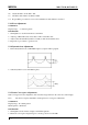
3. EW DRV (pin11) provides a complete EW drive waveform including parabola, corner and trapezoid
correction and feed to BIN (pin 5 of I401) to get a good control for pincushion / trapezoid / corner.
4. The top and bottom corner correction can be adjusted seperately.
4-3-5X-Ray Protection
1. To avoid X-ray hazard, a DC voltage generated at pin 6 of FBT and rectified by D417, C431 and divided
by R476, R477 and R478 come into pin 2 of TDA4856.
2. If this voltage is higher than 6.39 V, then TDA4856 will be activated to float HUNLOCK (pin17), H. DRV
( pin 8), B DRV (pin 6), VOUT1 (pin 12), VOUT2 (pin13). After that all deflection circuit stop working.
4-3-6G1, Blanking and Brightness
1. The vertical blanking signal comes from two ways. One is from pin 8 of I301 (TDA4866), the other is
from vertical sync (pin 33 of I701). These two positive vertical pulses through Q421 amplified and converted
into negative pulse and sent to G1 for vertical blanking.
2. In protection mode or an out-of- range situation HUNLock will send 5 V pulse to saturate Q429 and cutoff
Q420, then G1 will go down to -130V. During the mode change, Mute acts as same as HUNLock’s.
3. The brightness is controlled by CPU pin 3 through PNP transistor Q420. Q420 is a switch in conducted
(ON) status normally. The lower or higher control voltage will get low brightness or high brightness.