Semi-Auto BANDSAW BS-760M INSTRUCTION MANUAL MEGA MACHINE CO., LTD. DOC NO: BS760M-080410-100.
TABLE OF CONTENTS Item 1. 2. 3. 4. 5. Contents Page Introductory Illustrations 3 1.1. 3 Principal parts Specifications 4 2.1. Specifications 4 2.2. Standard Accessories 4 Installation 5 3.1. moving and lifting 5 3.2. Foundation layout and Set-up 6 Operation 8 4.1. Control Panel 8 4.2. Operating preparation 9 4.3. Manual Operation 10 4.4. Special Operation 10 4.5. Break -In Operation 11 Maintenance 12 5.1. Hydraulic Circuit 12 5.2.
FOREWORD We hope that the owner of this heavy-duty bandsawing machine will have years of trouble-free service. The machine has been built to the highest standards to enable fast accurate cutting to be obtained. In order that the best results can be achieved from your MEGA band saw we would ask all operators and maintenance engineers to READ THIS MANUAL CAREFULLY BEFORE STARTING UP THE MACHINE. The manual contains full instructions on installation, operation, lubrication, maintenance and trouble-shooting.
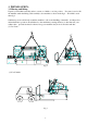
1. INTRODUCTORY ILLU1STRATIONS 1.
2 SPECIFICATIONS 2.1 SPECIFICATIONS MODEL BS760M PECIFICATION CUTTING CAPACITY AT 90 H BEAMS / PIPES MITRE CUTTING AT 60° H BEAMS / PIPES MITRE CUTTING AT 45° H BEAMS / PIPES MITRE CUTTING AT 30° H BEAMS / PIPES BLADE SIZE BLADE SPEED MOTOR OUTPUT SHIPPING VOLUMN WEIGHT Net/Gross ○ SOLID 460 MM DIA. □ SOLID 460 SQR. ◎ 460 MM O.D. □ / 760 x 400 ○ SOLID 420 MM DIA. □ SOLID 420 MM SQR. ◎ 460 MM DIA. □ / 590 x 400 MM ○ SOLID 330 MM DIA. □ SOLID 330 MM SQR. ◎ 460 MM DIA. □ / 500 x 400 MM ○ SOLID 220 MM DIA.
3. INSTALLATION: 3.1 Moving and lifting: Unpack your machine carefully, and use a crane or forklift to set it in position. If a crane is used to lift the machine attach the lifting cable carefully to the machine as shown in the fig 2. If forklift is used then fig 3. Sufficient space should be left around the machine to allow safe handling of materials , and inspection and maintenance operation.
3.2 Foundation layout and set-up: (1) Foundation: The foundation should be constructed of reinforced concrete and must be level and flat. After the proper leveling position has been obtained, anchor the machine with anchor bolts. The position of anchor bolts and floor dimensions are shown in fig 4: □ ○ Contact portion with floor Position of anchor bolts Fig. 4 ※ All leveling bolts should support the weight of the machine evenly .
(2) Leveling: The production accuracy of all precision machinery depends on the accuracy which the machine is installed . Manufacturing tolerance of the machine can only be guaranteed if the machine is firmly and properly installed . Once the machine is lowered on the prepared foundation . Machinist levels should be Used alternately on the vise slide plates and the work feed table , and adjust the left-and-right and fore-and-aft level of the machine with leveling bolt .
4. OPERATION 1. Control Panel (1) Emergency Stop -- This switch is used for emergency case to stop the machine only. Turn this switch clockwise makes power source on. When this switch is pressed, all machine's operation stop immediately. (2) Pilot Lamp -- This light will comes on when the power supply is on. (3) Power Switch Off -- This switch is used for turning off the power by depressing it. (4) Power Switch On -- This switch is used for turning on the power by depressing it.
4.2 OPERATING PREPARATION There are several steps will be taken before start the machine. (1) CHOOSE PROPER SAW BLADE : Select the saw blade best suited to the workpiece to be cut, Size and shape of the workpiece , and type of material should all be considered when selecting the saw blade to be used . There is a reference chart in chapter 7 which can help you to select the right saw blade and cutting conditions .
(8) SELECT THE SAW BLADE SPEED : There are 6 speeds provided : 25, 32, 42, 55, 70, 80 M/min If a optional variable speed drive is equipped the speed to be 20 to 80 M/Min steplessly. 4.3 MANUAL OPERATION : Place the workpiece to be cut on the work table , decide how long you want the off-cut , and carry out all the procedures as described above in [2] Operating Preparation. (1) Depress the RAISE button to lift the saw frame until the cutting edge of the saw blade clears the workpiece by 1/2 to 3/4 inch.
4.5 BREAK-IN OPERATION: When a new blade is used , be sure to first break in the blade before using it for extended operation. Failure to break in the blade will shorten the service lift of the blade ,and result in less than optimum efficiency. To break in the blade ,proceed as follow : (1) Reduce the blade speed setting to one half of its normal setting . (2) Lengthen the time required for cutting to 2-3 times that of normal.
5.Maintenance 5.
5.2 Oiling and Lubricant The operator should be responsible for the proper lubrication of quality of lubricant are given in the lubrication chart below : the machine. The grade and Oil Lubrication chart Lubricating Point Lubricant Quantity Oiling Frequency 1. Transmission Gear Box 2. Drive Wheel Bearing Driven Wheel Bearing Grease 20g 20g Thrice a year 3. Cutting Fluid Tank Cutting Oil Mixture (KH ULTRA COOL EX-2) 65 liters Daily 4.
5.3 OTHERS VARIABLES WHICH AFFECT BANDSAW BLADE LIFE 1. The Operator - The operator is the most important variable at any test. He can make or break any test and often has a great deal of influence over whose bandsaw blades are used. He can also be a good source of information on what is going on, competitive situations, relationships with manufacturers or distributors, etc. Don't ignore the operator. 2 .
12. Machine Condition-Whether a machine is old or new, and whether well maintained or not contributes to how well it runs and how long the band last. The better shape a machine is in, the better the bands will run. Poor machines ruin bandsaw blades. 13. Proper Vises - The work must be properly held. Side vises and top vises, if necessary, should be in good shape and able to firmly hold the work. Anything that moves will strip teeth. 14. Guides - The guides must support the band well while in the cut.
6. TROUBLE SHOOTING GUIDE The following charts contains some typical troubles along with the probable causes and remedies for each. 6.
6.2 Minor Operating Troubles and Remedies Symptom 1. Buttons do not function Probable Cause Remedy (1) Power disconnected (1) Connect (2) Circuit protector OFF (2) Turn on (3) Thermal relay activated (3)Push reset button (4) Safety interlocks that is a. Load workpiece a. No workpiece is clamped in the vice. b. Depress FRAME RAISE button b. The saw frame is not fully raised to c. Depress QUICK APPROACH the height preset. switch c.
7. REFERENCE CHARTS 7.1 Standard Cutting Chart Material JIS code S20C-S50C S9CK-S15C S53C-S58C SS-50 SS-41 SM-50 SCM-3 SCR-3.4 SNC-22 SNC-1 SNCM-22 SK-4 SUL-2 SKS-5 SKH-2 SUH-33 SKD-61 SKD-1 SUS-27 SUS-32 Blade Pitch TPI 3M 3M 3M 3M 3M 3M 3M 3M 3M 3M 3M 3M 3M 3M 3M 3M 3M 3M 3M 3M Blade Speed m/min 80 80 68 80 68 80 68 54 54 54 54 54 40 54 27.40 27.40 27 27 27.40 27.
7.2 Standard Cutting Chart Material AISI code No. 1108-1111 1112-1118 1115-1132 1137-1151 1212-1213 Brinell hardness Bhn 150-175 125-150 140-165 155-180 150-175 Blade speed fpm 220-260 240-270 220-260 180-200 240-270 Cutting rate Sq in/min 9.0-12.0 10.0-14.0 9.0-12.0 5.0- 8.5 10.0-14.0 1008-1013 1015-1035 1040-1064 1065-1095 1320-1330 150-175 160-175 160-180 180-205 200-220 220-260 240-270 180-210 120-140 140-180 7.0- 9.0 8.0-12.0 6.0- 9.0 5.0- 6.5 5.0- 7.
7.3 Standard Cutting Chart Material AISI code No.