Flachantenne Profi-Line Bedienungsanleitung
Inhaltsverzeichnis Sicherheitshinweise..................................................................03 1. Lieferumfang und Bezeichnungen................................04 - 05 2. Wahl des Standortes............................................................06 3. Montagemöglichkeiten......................................................08 3.1 Grundmontage der Antenne.........................................09 3.2 Montage an einem Mast.................................................10 3.
Sicherheitshinweise • Bitte lesen Sie vor dem Gebrauch dieses Produkts die Bedienungsanleitung sorgfältig durch und befolgen sie die Installations-, Montage- und Ausrichtungsanweisungen genau. • Jegliches elektrische oder magnetische Feld, das sich in der Nähe der Flachantenne befindet, kann zu schlechtem Empfang führen oder sogar dafür verantwortlich sein, dass das Gerät vollständig das Signal verliert. • Beschädigen Sie nicht das Kunststoffgehäuse der Antenne.
1. Lieferumfang und Bezeichnungen Bitte prüfen Sie vor der Installation, ob alle Teile vorhanden sind! Wichtig: Es ist nur ein LNB im Lieferumfang enthalten, je nachdem, welche Antenne Sie erworben haben (Single, Twin oder Quad) Nr.
1. Lieferumfang und Bezeichnungen Nr.
2. Wahl des Standortes Um ein Signal vom Satelliten zu empfangen, muss die Antenne im Freien installiert werden. Eine Installation in der Wohnung, bzw. durch die Fensterscheibe ist nicht möglich! Vergewissern Sie sich, dass am gewählten Standort die Antenne in Richtung Süden zeigt. Nutzen Sie hierzu einen Kompass zur groben Orientierung.
2. Wahl des Standortes Achtung: Häuser, Bäume und andere hohe Objekte können den Empfang mindern oder das Signal vom Satelliten komplett blockieren. Denken Sie auch daran, dass Bäume wachsen und in einiger Zeit den Empfang beeinträchtigen können. Guter Empfang: Schlechter Empfang: Auch Wettereinflüsse können zur Signalminderung führen! Starker Regen, Wind oder Schnee kann dazu führen, dass das Signal geschwächt wird. Dies ist aber in der Regel von kurzer Dauer.
3. Montagemöglichkeiten Es gibt verschiedene Möglichkeiten, wie Sie die Antenne befestigen können: 1. Montage an einem Mast 2. Montage an einer Wand 3.
3. Verschiedene Montagemöglichkeiten 3.1 Grundmontage der Antenne 1 Befestigen Sie die Winkelhalterung auf der Rückseite der Antenne mit vier Befestigungsschrauben M6 x 10. 3 2 Schrauben Sie die LNB Fixierungsschraube in die LNB-Vorrichtung. Stecken Sie anschließend das LNB ein und befestigen Sie diesen mit der LNB Klemmschraube. 4 Montieren Sie die Winkelhalterung auf den Befestigungsarm. Stecken Sie hierzu eine Befestigungsschraube M6 x 15 durch die Bohrung und fixieren Sie diese.
3. Montagemöglichkeiten 3.2 Montage an einem Mast 1 10 Montieren Sie die Befestigungsplatte A an den Befestigungsarm. Stecken Sie hierzu die Befestigungsschrauben M6 x 55 durch die beiden Bohrungen und fixieren Sie diese jeweils mit einer Schraubenmutter M6 auf der gegenüberliegenden Seite. 2 Stecken Sie die vier Befestigungsschrauben M6 x 75 durch die Befestigungsplatte A. 3 Stecken Sie die Befestigungsplatte A auf die Schrauben und befestigen Sie diese mit den Schraubenmuttern M6.
3. Verschiedene Montagemöglichkeiten 3.3 Montage an einer Wand 1 2 3 Halten Sie die Befestigungsplatte A an die gewünschte Montagestelle der Wand und zeichnen Sie die Bohrlöcher an. Bohren Sie die vier zuvor angezeichnten Löcher. Achten Sie darauf, welche Dübel, bzw. Schrauben Sie verwenden. Beispiel: 8 mm Dübel -> 8 mm Bohrer Montieren Sie die den Befestigungsarm an die Befestigungsplatte A.
3. Montagemöglichkeiten 3.4 Montage an einem Fenster 1 2 3 12 Montieren Sie die Fensterhalterung A an den Befestigungsarm. Nutzen Sie hierzu zwei Befestigungsschrauben M6 x 10. Montieren Sie die Fensterhalterung B an den Befestigungsarm. Nutzen Sie hierzu zwei Befestigungsschrauben M6 x 10. Hängen Sie die Antenne mit der Fensterhalterung A in die Falz des Fensters. Die Fensterhalterung B dient hierbei als Stütze.
4. Koaxialkabel vorbereiten und verlegen Achten Sie bei der Montage der F-Stecker, dass diese fachgerecht angebracht werden. Sind die F-Stecker nicht richtig montiert, kann es zu Signalverlust oder zu einem Kurzschluss kommen. Der Wetterschutz ist nur für den Außenbereich an der Antenne nötig. 15 mm Wetterschutz 8 mm F-Stecker 3 mm Verlegen Sie das Koaxialkabel von der Antenne zum Satelliten-Receiver. Achten Sie darauf, dass Sie beim Verlegen das Kabel nicht beschädigen oder keine Knicke entstehen.
5. Ausrichten der Antenne Richten Sie die Antenne nach Richtung Süden aus, wie in Punkt 2 „Wahl des Standortes“ beschrieben. Zur fachgerechtes Ausrichtung können Sie einen Satfinder, bzw. ein Messgerät nutzen. Alternativ schalten Sie Ihren Sat-Receiver ein und wechseln in das Menü mit der Anzeige von Signalqualität und -pegel.
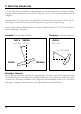
6. Skew Einstellung Signale in vertikaler (rot) und horizontaler (blau) Linie haben einen Versatz von genau 90º zueinander. Durch die unterschiedliche Position der Satelliten, abhängig von Ihrem Standort ist es möglich, dass die Signale nicht genau vertikal und horizontal auf das LNB treffen. Um dieses anzupassen, müssen Sie das LNB in die richtige Lage zu dem ausgesendeten Signal bringen. Diese Anpassung am LNB wird als „Skew Einstellung“ bezeichnet.
7. Fehlerbehebungen Wenn Sie ein schlechtes oder kein Signal empfangen, kann es folgende Gründe haben: • Vergewissern Sie sich, dass sämtliche Kabelverbindungen intakt sind und jede Verbindung ordnungsgemäß festgeschraubt ist. • Überprüfen Sie das Innere jedes F-Steckers auf Schmutz oder einen möglichen Stecker-Gehäuseschluss. • Überprüfen Sie erneut die Einrichtung der Antenne (horizontaler und vertikaler Winkel). Evtl. zeigt die Antenne Sie sich auf einen anderen Satelliten.
8. Technische Daten MERKMALE • Eingangsfrequenz: 10.7 - 12.75 GHz • Polarisation: Linear (vertikal / horizontal) • Antennenverstärkung: 33 dBi @ 12.75 GHz • LNB Ausgang: 1, 2 oder 4 • LNB Ausgangsfrequenz: 950 - 1.950 MHz / 1.100 - 2.150 MHz • L.O. Frequenz: 9.75 GHz / 10.6 GHz • LNB Verstärkung: min. 55 dB / max. 66 dB • Gain Flatness: 5 dB • Spannungsversorgung: 12 - 14 V DC (V) / 16 - 19 V DC (H) • Stromverbrauch: max.
Version 1.0 (Juli 2018) // Technische Änderungen, Druckfehler und Irrtümer vorbehalten. Megasat Werke GmbH | Industriestraße 4a | D-97618 Niederlauer www.megasat.tv | info@megasat.
Flat antenna Profi-Line user manual
Content Safety instructions.....................................................................03 1. Scope of delivery and designations..............................04 - 05 2. Selecting a location..............................................................06 3. Mounting options..................................................................08 3.1 Basic mounting of the antenna.....................................09 3.2 Mounting on a mast.......................................................
Safety instructions • Please read this manual carefully before using this product and follow carefully the installation, mounting and alignment instructions. • Any electrical or magnetic field near the flat antenna may cause poor reception or even cause the unit to completely lose the signal. • Do not damage the plastic housing of the antenna. The housing protects the antenna from moisture and weather.
1. Scope of delivery and designations Please check before installation, if all parts are present! Important: There is only one LNB included, depending on which antenna you purchased (single, twin or quad) No.
1. Scope of delivery and designations No.
2. Selecting a location To receive a signal from the satellite, the antenna must be installed outdoors. An installation in the apartment, or through the window is not possible! Make sure the antenna is facing south at the selected location. Use a compass for rough orientation. See this example if you want to receive the Astra 1 (19.
2. Selecting a location Attention: Houses, trees and other tall objects can reduce reception or completely block the signal from the satellite. Also keep in mind that trees can grow and affect reception in some time. Good reception: Bad reception: Also weather influences can lead to the signal reduction! Heavy rain, wind or snow can cause the signal to be weakened. But this is usually short-lived. Rain: In heavy rain, the satellite signal may temporarily stop.
3. Mounting options There are several ways you can attach the antenna: 1. Mounting on a mast 2. Mounting on a wall 3.
3. Mounting options 3.1 Basic mounting of the antenna 1 Attach the angle bracket to the back of the antenna with four M6 x 10 mounting screws. 3 Attach the angle bracket to the mounting arm. To do this, insert a fixing screw M6 x 15 through the hole and fix it. 2 Screw the LNB fixation screw into the LNB device. Then insert the LNB and fasten it with the LNB clamping screw. 4 To fix, turn a M6 x 15 fixing screw into the thread. This screw also adjusts the horizontal angle (azimuth) of the antenna.
3. Mounting options 3.2 Mounting on a mast 1 10 Mount the mounting plate A to the mounting arm. To do this, insert the M6 x 55 mounting screws through the two holes and fix them each with an M6 nut on the opposite side. 2 Insert the four mounting screws M6 x 75 through the mounting plate A. 3 Insert the mounting plate A onto the screws and fix them with the nuts M6.
3. Mounting options 3.3 Mounting on a wall 1 Hold the mounting plate A to the desired mounting position on the wall and mark the drilled holes. 2 Drill the four previously marked holes. Pay attention to which dowels or screws you use. Example: 8 mm dowels -> 8 mm drills 3 Mount the mounting arm to the mounting plate A. To do this, insert the M6 x 55 mounting screws through the two holes and fix them each with an M6 nut on the opposite side.
3. Mounting options 3.4 Mounting on a window 1 Mount the window holder A to the mounting arm. Use two screws M6 x 10 for this purpose. 2 Mount the window holder B to the mounting arm. Use two screws M6 x 10 for this purpose. 3 12 Hang the antenna with the window holder A in the fold of the window. The window holder B serves as a support. You can adjust the distance from the window to the outside wall with the two fixing screws M6 x 10 on the window holder A.
4. Prepare and lay coaxial cable When installing the F-connectors, make sure that they are installed correctly. Failure to correctly install the F connectors may result in signal loss or short circuit. The weather protection is only necessary for the exterior of the antenna. 15 mm 8 mm weather proof F-connector 3 mm Route the coaxial cable from the antenna to the satellite receiver. Make sure that you do not damage the cable during installation or that there are no kinks.
5. Align the antenna Richten Sie die Antenne nach Richtung Süden aus, wie in Punkt 2 „Wahl des Standortes“ beschrieben. Zur fachgerechtes Ausrichtung können Sie einen Satfinder, bzw. ein Messgerät nutzen. Alternativ schalten Sie Ihren Sat-Receiver ein und wechseln in das Menü mit der Anzeige von Signalqualität und -pegel. to receiver to antenna Sat-Finder Satfinder For orientation via a Sat-Finder, you must connect the Sat-Finder between the antenna and the receiver.
6. Skew setting Signals in the vertical (red) and horizontal (blue) line have an offset of exactly 90° to each other. Due to the different position of the satellites, depending on your location, it is possible that the signals do not meet exactly vertically and horizontally on the LNB. To adjust this, turn the LNB into the correct position to the transmitted signal. This adjustment to the LNB is called „skew adjustment“. The following figure shows the optimal setting of the LNB.
7. Troubleshooting If you receive a bad or no signal, it may have the following reasons: • Make sure all cable connections are intact and each connection is properly tightened. • Check the inside of each F connector for dirt or a possible connector shell. • Check again the setup of the antenna (horizontal and vertical angle). Possibly. the antenna points you to another satellite.
8. Specifications FEATURES • Input frequency: 10.7 - 12.75 GHz • Polarization: Linear (vertical / horizontal) • Antenna gain: 33 dBi @ 12.75 GHz • LNB output: 1, 2 or 4 • LNB output frequency: 950 - 1.950 MHz / 1.100 - 2.150 MHz • L.O. Frequency: 9.75 GHz / 10.6 GHz • LNB gain: min. 55 dB / max. 66 dB • Gain flatness: 5 dB • Power supply: 12 - 14 V DC (V) / 16 - 19 V DC (H) • Power consumption: max.
Version 1.0 (Juli 2018) // Technical changes, printing errors and errors reserved. Megasat Werke GmbH | Industriestraße 4a | D-97618 Niederlauer www.megasat.tv | info@megasat.