M LTW300 Series Earth Loop testers User Guide
G Safety warnings: n Safety Warnings and Precautions must be read and understood before the instrument is used. They must be observed during use. n The earth loop impedance test creates a temporary low resistance path between live and earth for the duration of the test. This is particularly hazardous with both an instrument fault and an installation fault. Working practice and hazard avoidance must take care of this risk.
Contents Introduction General introduction Unpacking the carton LCD display Top panels Additional controls on the LTW335 Keypad controls Range knob controls Connection panel Lid open/closure Preparations for use Preliminary test lead Ingress moisture General operating instructions Backlight operation Test leads Test lead connection Loop testing Description of test methods No-trip test (all instruments) Symbols used during a normal loop test High current test (all instruments) High resolution test (LTW425 on
1. Introduction Thank you for purchasing the Megger Earth Loop impedance tester. For your own safety and to get the maximum benefit from your instrument, please ensure that you read and understand the following safety warnings and instructions before attempting to use the instruments.
2. General description The LTW300 series loop testers are designed for the measurement of loop resistance (Impedance) of fixed electrical installations on single and 3 phase systems. 2.1 Unpacking the carton Unpack the carton contents carefully. There are important documents that you should keep for future reference. Please complete the pre-paid warranty card and return it to Megger as soon as possible to help us reduce any delays in supporting you should the need arise.
2.
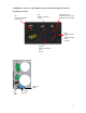
2.3 Top panels Test lead connections See section 2.
2.4 Additional controls on the LTW335 (storage and downloading instrument): 2.4.1 Keypad controls OK Confirms a test result delete request ESC Aborts a result save process UP/DOWN arrows: Scrolls through circuit and distribution board numbers NEXT Selects test type Job, Distribution board, Circuit, Phase etc STORE Stores last test result LAST As next 2.4.
2.5 Connection panel Single or 3 Phase connection Warning Read user guide Maximum 300V Phase to earth Earth, Neutral or 2 phase connection nd USB connection to computer port LTW335 only 2.6 Lid open/closure 1. Open lid by lifting up front panel tab (1). 2. Foldaway underneath instrument (2 & 3) and push into retaining slot (4).
3. Preparations for use The instrument is supplied with batteries already fitted. However when fitting replacement batteries, refer to section 10.2: WARNING: Never use the instrument with the battery cover removed. Incorrect battery cell polarity can cause electrolyte leakage, resulting in damage to the instrument. Always fit a complete new set of batteries, never mix old and new cells. Check that the Battery level indicator displays a full charge before using the instrument.
WARNING: A plug severed from the power cord must be destroyed, as a plug with bare conductors is hazardous in a live socket outlet. 4.3 Test lead connection The supplied test leads should be connected to the appropriate sockets on the rear of the instrument marked L0/L2 and L1. Standard test probes and crocodile clips and mains socket test lead are supplied for connection to the circuit under test.
5. Loop testing Different loop testing options are available depending on the instrument used as below: Instrum ent NOTRIP High Current MaxZ R1+R2 LTW31 5 LTW32 5 LTW33 5 LTW42 5 n n n n n n n n n n n HIGH Resolution Result storage and download. 50 V 440V 100 V 280 V n n n n n n n n n 5.1 Description of test methods 5.1.1 No trip test - (All instruments) Designed not to trip circuits protected by an RCD ≥30mA.
If a low level of electrical noise is detected in mode 2, the [ ] will be displayed to the right of the [ ] symbol. The test time will be extended up to a further 10 seconds to improve the accuracy of the test results. This only applies if the tester, is running in mode 2, see section 5.2.1. If a high level of electrical noise is detected the symbol [ ] will be displayed. This indicates that excessive noise was detected during the test.
The symbols [ ] and [ ] may appear during the test. Refer to section 5.1.1.2 (Symbols) for an explanation of their meaning. 5.2.2.2 Phase to neutral loop test Phase to Neutral testing can be made using the No-Trip test, as described above for the Phase to earth test. However a High Current test will not trip RCDs when making a P-N test and it is recommended that a High Current test is used for this measurement. 5.2.
[High Current] test instead of [No Trip] test, with the leads connected to the supply. In which case pressing the [TEST] button will start a test. Subsequent connection of test leads will run the AUTO START test. AUTO START can be disabled in the SETUP procedure as described in section 8. 5.3.2 High current Phase to Neutral loop test Repeat test 5.3.1 with the Green lead connected to the Neutral conductor. This test can also be performed using the mains socket test lead, using the RED and BLUE connectors.
5.6 Possible sources of error The displayed reading depends on a measurement of the supply voltage and therefore noise or transients caused by other equipment during the test could cause an error in the reading. One way to check for these is to do two tests and look for any difference in value. The instrument may detect some sources of noise and warn the user. Test results may be adversely affected, by supply voltage fluctuations, voltage glitches, spikes or electrical ‘noise’ during a measurement.
The LTW325, LTW335 and LTW425 are able to derive the (R1+R2) circuit impedance from tests made on a live installation. It is not possible to isolate R1 or R2 separately. Application note for Zref and R1+R2 measurement: On initial verification of a new electrical installation, the value for R1+R2 should be obtained by continuity testing methods (dead testing) as per BS 7671:2001 or other international standards.
To measure the Phase-Neutral voltage, connect the RED and BLUE plug of the mains socket test lead to the instrument. To measure the voltage of the electrical supply using the RED / GREEN test leads: 1. Set the instrument to the [V/Hz] range. 2. Connect the GREEN test lead to the Protective Earth (PE) and the RED test lead to the phase to be measured. 3. The instrument will display the voltage and the frequency. 4.
Note: To change any setting before saving a result, scroll down through the result using the NEXT/LAST keys. Change the distribution board, circuit number etc, using the UP/DOWN keys and press OK. 7.4 To recall test result: 1. 2. 3. 4. 5. 6. Set the lower range knob to RECALL. The last unique record number is displayed. Use the UP/DOWN keys to select the test record to recall. Use the LAST or NEXT keys to scroll through job number, distribution board, circuit number etc, associated with the test result.
8. SETUP menu The SETUP mode allows the following functions to be configured: Section option Function AoFF AUTO OFF time The automatic switch off time of the instrument can be extended if required. Buzzer ON/OFF The buzzer can be disabled for working in office environments. Touch Voltage limit This is the voltage the earth wiring or CPC can be allowed to rise to, whilst performing a loop test. This is set to 50 V but can be adjusted to 25 V where necessary.
9. Subtract the first test result from the second test result to obtain the additional loop resistance created by the new lead set. If the result is negative, the second lead set resistance is less that the standard supplied lead set and should not be used for loop testing on this instrument. If the result is greater than 0.99 Ω, the instrument will not be able to take fully into account of the extra lead resistance.
9. Warning and status messages 9.1 Loop test inhibit or premature termination of a loop test: A loop test may stop or even be prevented from starting if there is a connection problem with the test leads or instrument fuse, an earth problem on the circuit being tested, or a supply voltage or frequency out of range. Test inhibit If an out of range voltage or frequency exists on the circuit under test, testing will be automatically inhibited and the corresponding information will be displayed.
Instrument malfunction. If repeated follow returns procedure. Any E followed by a number, ie E001, E002… Faulty, stuck key or switch position. Loop test result out of display range. Over voltage warning. For LTW315 the warning will be <280 V. No Zref value stored, or test result lower than stored Zref. Zref measurement required before an R1+R2 measurement can be made. Supply frequency out of range. Display switches between frequency and voltage. Display shows <49.00Hz or >51.00Hz.
10.2 Procedure to replace batteries WARNING: Do not switch the instrument on with the battery cover removed. The rear cover must not be opened if the test leads are connected. 1. 2. 3. 4. 5. 6. Switch off the instrument and disconnect (the instrument) from any electrical circuits. To avoid the possibility of electric shock, do not press the test button or touch the fuse when changing batteries. To remove the rear cover, remove the retaining screw from the rear of the battery cover and lift the cover off.
13. Technical specification 13.1 General specification Only values with tolerances or limits are guaranteed data. Values without tolerances are for information only. Accuracy; All accuracy statements are based on: Ambient temperature: 23ºC ± 2ºC Nominal source voltage: 230 V a.c ± 1% Voltage measurement. (a.c only) Accuracy: Frequency measurement Range: Accuracy: 50 V to 440 V ±2% ±1 V 25 Hz to 99.99 Hz ±0.1 Hz A warning will be shown if applied voltage exceeds 440 V.
Environmental Temperature and humidity Operating Range: -10°C to +60°C Operating Humidity: 90% R.H. non-condensing at +40°C max. Storage Range: -25°C to +70°C Maximum altitude: 2000m to full safety specification Dust and water ingress: IP54 Safety Designed to IEC61010-1, and IEC 61557 part3 1997 Designed for 300 V to Earth Category IV, With Phase to Phase voltages to 440 V. Fuse protected to 600 V rms a.c. A warning will be shown if applied voltage exceeds 440 V.
15. Repair and Warranty The instrument contains static sensitive devices, and care must be taken in handling the printed circuit board. If an instrument’s protection has been impaired it should not be used, but send for repair by suitably trained and qualified personnel.
M Megger Limited Archcliffe Road, Dover Kent CT17 9EN England T +44 (0)1 304 502101 F +44 (0)1 304 207342 E uksales@megger.com Megger 4271 Bronze Way, Dallas, Texas 75237-1019 USA T +1 800 723 2861 (USA ONLY) T +1 214 333 3201 F +1 214 331 7399 E ussales@megger.com Megger Z.A. Du Buisson de la Couldre 23 rue Eugène Henaff 78190 TRAPPES France T +33 (0)1 30.16.08.90 F +33 (0)1 34.61.23.77 E infos@megger.