
Instructions


21
8. SETUP menu
The SETUP mode allows the following functions to be configured:
Section
option
Function
Options
Factory
setting
AoFF
AUTO OFF time
The automatic switch off time of the instrument can be
extended if required.
2min / 20min
2min
buZZ
Buzzer ON/OFF
The buzzer can be disabled for working in office
environments.
ON / OFF
ON
tVl
Touch Voltage limit
This is the voltage the earth wiring or CPC can be allowed to
rise to, whilst performing a loop test. This is set to 50 V but
can be adjusted to 25 V where necessary.
25V / 50V
50V
Null
Lead null
Allows additional test lead resistance of longer or fused test
leads to be nulled from the test results. See 8.2 below.
0.00 Ω
to
0.99 Ω
0.00 Ω
tESt
No-trip Test mode
The instrument can be set to perform a 10 second loop test,
or an automatic loop test that extends the test time up to 20
seconds, if it detects any supply changes that could affect
test results.
10s, Auto
Auto
AuSt
Automatically starts loop test
Starts loop test on contact with circuit without the need to
press the TEST button.
ON, OFF
ON
RSt
Restores factory settings
Restore
-
8.1 Setup option selection
1. Select [SETUP] on the lower range knob. Instrument firmware revision will be displayed briefly. Wait for
the instrument to display SEt.
2. Press the [ ] key to cycle through the SETUP options until the required setup option is displayed.
3. Press [TEST] to select the function.
4. Press the [ ] key to cycle through the options available for that function. Once the desired option is
displayed press [TEST] to store setting. The display will show “Ok” and then return to the function
heading. To select another function, repeat from step 2.
5. To go back to main menu ‘SEt’, press [PFC] button.
6. To exit SETUP mode turn the lower range knob to any other position.
8.2 Fused or long test lead length
The test lead resistances of the supplied test leads are already calibrated into the instrument. However,
should the optional fused leads or a longer lead set be used, the additional resistance can be set in the
instrument so as not to affect the loop test result.
To establish additional resistance of new lead set:
NOTE: The high current loop test should be used for this adjustment to ensure accurate measurements.
1. Ensure the top range knob is set to [Z] (does not apply to the LTW315).
2. Select the High Current test range on the instrument lower range knob.
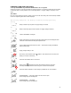
3. Connect the standard (supplied) RED and GREEN test leads to the instrument.
4. Connect the RED test lead to the Phase conductor.
5. Connect the GREEN test lead to the Earth conductor or to the Neutral conductor if the circuit is RCD
protected.
6. Press the [TEST] key. The measured loop value is displayed.
7. Note down the loop test value.
8. Repeat the same loop test with the new test leads and note down the value. This value
should be higher than the first test result.