
User manual


Inputs and Outputs
The MX-1004 has 10 inputs and accepts both graphics and video signals, which come from computers
(DVI or VGA), composite, and component video sources respectively. You can pick up four of the ten
inputs and then display four of them simultaneously on the same screen. Figure 2 shows the rear
panel connectors of
a MX-1004 and Table 1 illustrates how you can connect video devices and display
to the
MX-1004.
*Default: Turn on the MX-1004 then switch both three DIP switches simultaneously up
and down to factory default mode.
*
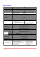
These IO ports support various resolution from 640x480 up to 1920x1200, for more
detail of the supported modes, please refer to the Appendix – Supported
Resolution.
Table 1: Input/Output Connectors
Input Connector Video Source
[1] DVI
[2] VGA — with a DVI-to-VGA adapter
(DVA01)
[3] Component (YPbPr) — with a DVI-to-VGA adapter (DVA01) and a
VGA-to-component breakout cable (VYPBA01)
[4] 1x DVI + 1x VGA — with a DVI-to-DVI/VGA breakout cable (DDVY01)
DVI-x
YPbPr-x/VGA-x
[x = 1~3]
[5] 1x DVI + 1x Component (YPbPr) — with a DVI-to-DVI&VGA breakout cable
(DDVY01) and a VGA-to-component breakout cable (VYPBA01)
[1] DVI
VGA-4
[2] VGA — with a DVI-to-VGA adapter
(DVA01)
CVBS-1 ~ CVBS-4 [1] Composite — with a RCA cable
Bridge Connector 2x DVI*
Output Connector Display
[1] DVI display
[2] VGA display — with a DVI-to-VGA adapter
(DVA01)
DVI-I OUT
[3] 1x DVI display + 1x VGA display — with a DVI to DVI&VGA breakout cable
(DDVY01)
It is CRITICAL to have the DVI-to-DVI cables connected to the CONN1-CONN1 & CONN2-CONN2
sockets on the
MX-1004 for normal operation & firmware update. Please have the bridge
connectors linked at any time.
Figure 2: Rear Panel
Page 8 of 18