
Specifications


9. Inspect the electrical connectors (encoder cable plug and encoder body) for loose
wires, loose fits, and any visual damage. Clean connections and/or replace
components as necessary.
If the "test" above fails or is in question, contact your local Melco service
representative for advise. Refer to Section 3 of this manual for the installation
procedure for a new Z shaft encoder.
Z Shaft Encoder Calibration
"FACTORY SERVICE ADVISED"
CAUTION! Failure to properly calibrate the Z shaft encoder after replacing it, may
cause damage when attempting to operate the machine.
Note: This procedure requires the use of a special service tool: the Melco 10 needle
headup fixture (p/n 995673-01).
1. Install the Z shaft encoder as described in Section 3 of this manual.
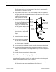
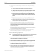
2. With the embroidery peripheral turned OFF, remove the cover #4. Then remove
the EMI Box Cover to gain access to the CPU Board. (Refer to specific instructions
for removal.) This will expose the three LEDs along the top left of the CPU.
Note: To perform this procedure, it is important that the peripheral does
not "download." To insure this condition remove the network cable (or
boot disk if the disk drive option is installed).
3. With the network cable removed (or boot disk not inserted into a disk drive
option), turn ON the embroidery peripheral.
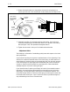
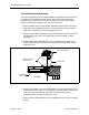
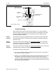
4. Position the Melco 10 needle headup fixture (p/n 995673-01) into the headup
alignment hole in the top of head #4, just in front of the thread tree (see Figure
2-16).
headup alignment
pin tool
Figure 2 - 16
2 - 18 Head Section
EMC 10/4 Technical Manual Melco Embroidery Systems