
Specifications


4. To remove the panel assembly completely you must disconnect all harness
connections associated with the switches in the panel assembly.
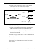
5. For reinstalling the start/stop panel assembly refer to the diagram in Figure 2-2
for reattaching the harness connections to the various switches in the panel.
Keyboard Panel Assembly
1. To remove the keyboard panel assembly from between the tensioners of the
middle two heads, you must first remove the disk drive panel assembly.
2. Remove the two screws holding the panel assembly at the rear tensioner cover.
3. Remove the four screws at the front and any ground wire connection associated
with the keyboard panel assembly.
4. To remove the assembly completely out of its location you must disconnect the
keyboard and display harness connections.
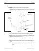
Tensioner Covers
Left Cover
To remove the left end tensioner cover, remove one screw at the rear (going into
the rear tensioner cover) and remove three screws at the front. Slide the cover to
the left to remove it.
[] nc
[] c
STOP
[] no
[] nc
[] c
FRAME
[] no
[] nc
[] c
START
[] no
White
or Red
Red or
White
either
Black
either
Black
Red (P1)
White (P3)
Black (P2)
black
black
black
(P5)
(P6)
(P4)
E-STOP
REAR VIEW
START/STOP ASSEMBLY PANEL
Figure 2 - 2
Tensioner Covers 2 - 3
110279-01, Rev B 2. Service Maintenance (except head and trimmer)