ConnectX®-2 VPI Dual Port QSFP and SFP+ Card User’s Manual P/N: MHZH29-XTR, MHZH29-XSR Rev 1.0 www.mellanox.
Rev 1.0 NOTE: THIS HARDWARE, SOFTWARE OR TEST SUITE PRODUCT (“PRODUCT(S)”) AND ITS RELATED DOCUMENTATION ARE PROVIDED BY MELLANOX TECHNOLOGIES “AS-IS” WITH ALL FAULTS OF ANY KIND AND SOLELY FOR THE PURPOSE OF AIDING THE CUSTOMER IN TESTING APPLICATIONS THAT USE THE PRODUCTS IN DESIGNATED SOLUTIONS. THE CUSTOMER'S MANUFACTURING TEST ENVIRONMENT HAS NOT MET THE STANDARDS SET BY MELLANOX TECHNOLOGIES TO FULLY QUALIFY THE PRODUCTO(S) AND/OR THE SYSTEM USING IT.
ConnectX-2 VPI InfiniBand and Ethernet Adapter Card User’s Manual Rev 1.0 Table of Contents Table of Contents List of Figures List of Tables 3 4 5 Revision History 6 7 About this Manual 7 Chapter 1 8 Chapter 2 Overview 1.1 Adapter Cards 1.2 Mellanox Part Numbering Legend 1.3 Finding the GUID/MAC and Serial Number on the Adapter Cards 8 9 10 VPI Adapter Card Installation 12 2.1 2.2 2.3 2.4 2.
Rev 1.
ConnectX-2 VPI InfiniBand and Ethernet Adapter Card User’s Manual Rev 1.
Rev 1.0 Revision History This document was printed on 11/3/09. Table 1 - Revision History Table 6 Date Rev October 2009 1.
ConnectX-2 VPI InfiniBand and Ethernet Adapter Card User’s Manual Rev 1.0 About this Manual This User’s Manual describes Mellanox Technologies ConnectX®-2 VPI IB and Ethernet PCI Express x8 adapter cards. It provides details as to the interfaces of the board, specifications, required software and firmware for operating the board, and relevant documentation. Intended Audience This manual is intended for the installer and user of these cards.
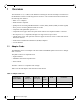
Rev 1.0 1 Overview Overview This document is a User’s Manual for Mellanox Technologies network VPI adapter cards based on the MT25408 ConnectX®-2 VPI integrated circuit device. The cards described in this manual have the following main features: • IBTA v1.2.1 compliant • IEEE Std 802.3 compliant • QSFP port for connecting InfiniBand traffic at 10Gb/s (SDR), 20Gb/s (DDR), or 40Gb/s (QDR) • SFP+ port for connecting Ethernet traffic at 10 Gb/s • Compliant with QSFP MSA spec Rev. 1.
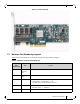
ConnectX-2 VPI InfiniBand and Ethernet Adapter Card User’s Manual Rev 1.0 Figure 1: Component Side 1.2 Mellanox Part Numbering Legend Table 4 describes the Mellanox Technologies adapter cards part numbering legend.
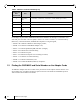
Rev 1.0 Overview Table 4 - Mellanox Cards Part Numbering Key Adapter Card OPN MHTS#I-XBR Field Decoder I Host Interface X = PCI-X, 4 = PCIe x4, 8 = PCIe x8, 9 = PCIe (SerDes @ 5.
ConnectX-2 VPI InfiniBand and Ethernet Adapter Card User’s Manual Rev 1.
Rev 1.0 VPI Adapter Card Installation 2 VPI Adapter Card Installation 2.1 Hardware and Software Requirements Before installing the adapter card, please make sure that the system meets the hardware and software requirements listed in Table 5, “Hardware and Software Requirements”. Refer to Chapter 3,“Driver Software and Firmware” on page 17 for download and installation instructions.
ConnectX-2 VPI InfiniBand and Ethernet Adapter Card User’s Manual Rev 1.0 3. During Lightning - Electrical Hazard During periods of lightning activity, do not work on the equipment or connect or disconnect cables. 4. Copper InfiniBand Cable Connecting/Disconnecting Copper InfiniBand cables are heavy and not flexible, as such they should be carefully attached to or detached from the connectors. Refer to the cable manufacturer for special warnings and instructions. 5.
Rev 1.0 VPI Adapter Card Installation The adapter cards are shipped without optical modules. Approved modules must be purchased from Mellanox. The OPNs for the approved Mellanox modules are MFM1T02A-SR and MFM1T02A-LR. The figure below shows the Mellanox approved SFP+ module. Note: SR and LR modules not recommended by Mellanox may not work with the adapter. Figure 3: SFP+ Transceiver Module 2.4.1 Inserting the Optical Transceiver Module To insert the module into the cage: 1.
ConnectX-2 VPI InfiniBand and Ethernet Adapter Card User’s Manual Rev 1.0 Note: When installing cables make sure that the latches engage. Note: Always install and remove cables by pushing or pulling the cable and connector in a straight line with the card. To remove a cable, disengage the locks and slowly pull the connector away from the port receptacle. Both LED indicators will turn off when the cable is unseated. Cables, especially long copper cables, can weigh a substantial amount.
Rev 1.0 VPI Adapter Card Installation 3. Remove any cable supports that were used to support the cable’s weight. 2.5 Cable Lengths Mellanox Cards support up to 40 Gb/s IB and Ethernet over the QSFP port, and up to 10Gb/s on the SFP+ connector. 2.5.1 InfiniBand Connectivity These Mellanox Cards support QSFP passive copper connectivity up to 7 meters, and active cable support up to 50 meters. 2.5.2 Ethernet Connectivity These Mellanox Cards support ethernet connectivity as defined in IEEE Std 802.3.
ConnectX-2 VPI InfiniBand and Ethernet Adapter Card User’s Manual 3 Driver Software and Firmware 3.1 Driver Software Rev 1.0 For Linux, download and install the latest OpenFabrics Enterprise Distribution (OFED) software package available via the Mellanox OpenFabrics Web site at: http://www.mellanox.com => Downloads => InfiniBand/VPI SW/Drivers. Follow the installation instructions included in the download package. 3.
Rev 1.0 Adapter Card Interfaces 4 Adapter Card Interfaces 4.1 I/O Interfaces Each adapter card includes the following interfaces: • QSFP Optical Connector • SFP+ Ethernet Connector • PCI Express x8 edge connector • I/O panel LEDs • I2C compatible connector (for debug) Port 1 connects to the IB port of the device, while port 2 connects to the Ethernet port of the device. See Figure 7,“Port Numbering” Figure 7: Port Numbering Port 1 IB port Port 2 Ethernet 4.1.
ConnectX-2 VPI InfiniBand and Ethernet Adapter Card User’s Manual Rev 1.0 4.1.3 PCI Express Interface The ConnectX-2 adapter cards support PCI Express 2.0 (1.1 compatible) through an x8 edge connector. 4.1.4 LED Assignment The board has I/O LEDs located on the I/O panel. The green LED, when lit, indicates that the driver is running and a valid physical connection between nodes exists. If the green LED is blinking, it indicates a problem with the physical link.
Rev 1.0 Adapter Card Interfaces Figure 9: I2C Connector 4.2 Power All adapter cards receive 12V and 3.3V power from the PCI Express Edge connector. All other required power voltages are generated by on-board switch mode regulators. See “Specifications” on page 25. 4.3 Memory The adapter cards support multiple memory devices through the PCI Flash, and I2C-compatible interfaces.
ConnectX-2 VPI InfiniBand and Ethernet Adapter Card User’s Manual 4.4 Rev 1.0 VPD Layout for these Adapter Cards The PCI VPD (Vital Product Data) layout, for each of the described Mellanox Technologies ConnectX-2 VPI adapter cards comply with the format defined in the PCI 2.3 Specification, Appendix I. All ConnectX-2 adapter cards have the same PCI VPD layout. 4.4.
Rev 1.
ConnectX-2 VPI InfiniBand and Ethernet Adapter Card User’s Manual 5 Rev 1.0 Replacing a Tall Bracket With a Short Bracket This section provides instructions on how to remove the tall bracket of a standard Mellanox Technologies adapter card and replace it with a short one.
Rev 1.0 Replacing a Tall Bracket With a Short Bracket Note: If the old gasket is still on the card, remove it before installing the new bracket. Make sure that only one gasket is used. 3. Place the bracket onto the card until the screw holes line up. Note: Do not force the bracket onto the card. You may have to gently push the LEDs using a small screwdriver to align the LEDs with the holes in the bracket. 4. Using the screws and washers saved from the procedure above step 1.
ConnectX-2 VPI InfiniBand and Ethernet Adapter Card User’s Manual Rev 1.0 Appendix A: Specifications A.1 Board Mechanical Drawing and Dimensions All of the cards covered in this User’s Manual have the same mechanical drawing and share the same dimensions as depicted in Figure 13. Note: All dimensions are in millimeters. Figure 13: Schematic of the ConnectX-2 MHZH Adapter Card J3 – Flash Jumper J1 – I2C Connector 15.00 3.65 33.35 43.13 57.13 J1 U4 L7 U11 U22 L15 Q3 68.
Rev 1.0 A.2 EMC Certification Statements Table 11 lists the approved certification status per adapter card in different regions of the world. . Table 11 - Adapter Cards Certification Status HCA Card P/N FCC Class (USA) EN Class (Europe) ICES Class (Canada) VCCI (Japan) MHZH29-XSR A A A A MHZH29-XTR A A A A A.2.1 FCC Statements (USA) Class A Statements: § 15.
ConnectX-2 VPI InfiniBand and Ethernet Adapter Card User’s Manual Rev 1.0 A.2.2 EN Statements (Europe) EN55022 Class A Statement: Warning This is a class A product. In a domestic environment this product may cause radio interference in which case the user may be required to take adequate measures. A.2.3 ICES Statements (Canada) Class A Statement: “This Class A digital apparatus complies with Canadian ICES-003. Cet appareil numérique de la classe A est conforme à la norme NMB-003 du Canada.” A.2.
Rev 1.0 A.3 MHZH29-X[ST]R Specifications Table 12 - Specifications for MHZH29-XTR Physical Power and Environmental Size: Air Flow: QSFP40Gb/s Connector: 2.71in. x6.60in. (68.90mm x 167.65mm) 200LFM @55°C InfiniBand (Copper and optical) Max power per port 2.0 W. Voltage: Maximum Power: 12V, 3.3V 16.5W plus 3.5W for active cables Typ Power: 12.0W for passive cables only 15.5W for active optic modules Temperature: 0°C to 55°C SFP+ Connector Ethernet (Copper and optical) Max power per port 1.
ConnectX-2 VPI InfiniBand and Ethernet Adapter Card User’s Manual Rev 1.0 Appendix B: Interface Connectors Pinout B.1 I2C-Compatible Connector Pinout Figure 7: Compatible Connector Plug and Pinout 4 3 2 1 5 5 1 2 3 4 Table 13 - I2C-compatible Connector Pinout Connector Pin Number Signal Name 1 SPSDA 2 SPSCL 3 GND 4 NC 5 NC B.
Rev 1.0 B.
SDA GND RX3p RX3n GND SCL RX1n ResetL RX1p 15 GND 14 VccRx 13 19 12 ModSelL 20 GND 21 RX2n 22 RX2p 23 GND 24 RX4n 25 RX4p 26 GND 27 ModPrsL 28 IntL 29 VccTx 30 Vcc1 31 LPMode 32 GND 14 13 12 11 1 0 9 8 7 6 5 4 3 2 1 GND 11 1 0 9 18 8 17 7 GND 15 TX2n 33 TX3p TX2p 6 16 5 TX4p 16 GND 34 TX3n TX4n 4 TX4n TX4p 19 18 17 GND 35 GND ModSelL 3 GND ResetL 36 TX1p SCL 2 TX2p SDA 1 TX2n GND 37 TX1n GND 3 8 TX1n 3 7 TX1p 3 6 GND 3 5 TX3n 3 4 TX3p 3 3 GN
Rev 1.0 B.4 SFP+ Connector Pinout Figure 15: Rear View of Module With Pin Placement Top 13.70 8.
ConnectX-2 VPI InfiniBand and Ethernet Adapter Card User’s Manual Rev 1.0 Table 15 - SFP+ Connector Pinout Pin Symbol Name Description 1 VeeT Transmitter Ground (Common with Receiver Ground) a 2 TX_Fault Transmitter Fault.b 3 TX_Disable Transmitter Disable. Laser output disabled on high or open. c 4 SDA 2-wire Serial Interface Data Line d 5 SCL 2-wire Serial Interface Clock Line d 6 MOD_ABS Module Absent.
Rev 1.0 Appendix C: Avertissements de sécurité d’installation (Warnings in French) 1. Instructions d’installation Lisez toutes les instructions d’installation avant de brancher le matériel à la source d’alimentation électrique. 2. Température excessive Ce matériel ne doit pas fonctionner dans une zone avec une température ambiante dépassant le maximum recommandé de 55°C (131°F). Un flux d’air de 200LFM à cette température ambiante maximale est nécessaire.
ConnectX-2 VPI InfiniBand and Ethernet Adapter Card User’s Manual Rev 1.0 7. Codes électriques locaux et nationaux Ce matériel doit être installé dans le respect des codes électriques locaux et nationaux. This equipment should be installed in compliance with local and national electrical codes. 8.
Rev 1.0 Appendix D: Sicherheitshinweise (Warnings in German) 1. Installationsanleitungen Lesen Sie alle Installationsanleitungen, bevor Sie das Gerät an die Stromversorgung anschließen. 2. Übertemperatur Dieses Gerät sollte nicht in einem Bereich mit einer Umgebungstemperatur über der maximal empfohlenen Temperatur von °C (°F) betrieben werden. Es ist ein Luftstrom von 200 LFM bei maximaler Umgebungstemperatur erforderlich. Außerdem sollten mindestens 8 cm (3 in.
ConnectX-2 VPI InfiniBand and Ethernet Adapter Card User’s Manual Rev 1.0 7. Regionale und nationale elektrische Bestimmungen Dieses Gerät sollte unter Beachtung der regionalen und nationalen elektrischen Bestimmungen installiert werden. 8. Strahlenkontakt Achtung – Nutzung von Steuerungen oder Einstellungen oder Ausführung von Prozeduren, die hier nicht spezifiziert sind, kann zu gefährlichem Strahlenkontakt führen..