AtmoCONTROL SOFTWARE MANUAL 100% ATMOSAFE. MADE IN GERMANY. www.memmert.com | www.atmosafe.
Manufacturer and customer service Memmert GmbH + Co. KG Willi-Memmert-Straße 90–96 D-91186 Büchenbach Deutschland/Germany Phone: +49 (0)9122 925-0 Fax: +49 (0)9122 14585 E-mail: sales@memmert.com Internet: www.memmert.com Customer service: Service hotline: +49 (0)9171 9792 911 Service fax: +49 (0)9171 9792 979 E-mail: service@memmert.com © 2014 MEMMERT GmbH + Co.
AtmoCONTROL About this manual Purpose and target group This user manual describes the installation and use of the MEMMERT programming software AtmoCONTROL. It is intended for use by trained personnel of the operator, who have the task of programming/operating MEMMERT appliances. If you intend to work with the software, please read this manual carefully before starting. Familiarise yourself with the software and simulate various tests before transferring programmes to the appliance.
AtmoCONTROL Contents 1. Introduction 1.1 1.2 Description........................................................................................................................... 6 Supported MEMMERT appliances and parameters ............................................................ 6 2.1 2.2 System requirements ........................................................................................................... 7 Installing AtmoCONTROL ........................................................
AtmoCONTROL 6. 7. Printing Options 7.1 7.2 7.2.1 7.2.2 7.3 7.4 Language ........................................................................................................................... 29 USER-ID .............................................................................................................................. 29 Description ...................................................................................................................... 29 Use..................................
AtmoCONTROL 1. Introduction 1.1 Description AtmoCONTROL is a software for programming and logging MEMMERT appliances of the generation 2012 of appliances (from October 2012) with Ethernet and/or USB interface and corresponding equipment.
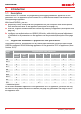
AtmoCONTROL 2. Installation 2.1 System requirements Category Minimum system requirements Processor Pentium 1 GHz Main memory 1 GB Available free space on hard drive 4 GB Graphics VGA graphics and colour monitor Interfaces an available USB or Ethernet interface Operating system Windows 7, Windows 8 2.2 Installing AtmoCONTROL You must have administrator rights to be able to install AtmoCONTROL. Start the installation file AtmoControlSetup.exe from the USB storage medium provided.
AtmoCONTROL 3.2 Programme interface The main programme interface window of AtmoCONTROL is divided into the following areas: 2 1 6 5 3 4 1 2 3 4 5 6 Menu bar (see section 3.2.1) Toolbar (quick access to most important functions, see section 3.2.
AtmoCONTROL 3.2.1 Menu bar Device 1 2 3 4 5 1 2 3 4 5 6 7 Program Connect online via Ethernet Connect offline from USB device Connect offline from database Disconnect device Disconnect all devices 6 7 8 9 10 11 Protocol New 12 Import... Load 13 Export... Save Save As...
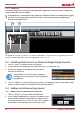
AtmoCONTROL 3.2.3 Status bar The status bar gives an overview of the appliances logged on to AtmoCONTROL. Appliances can be added and removed again. If the appliance is connected to the computer via Ethernet and it has already been logged on once, it is automatically recognised and the current operating state (temperature, alarms) is displayed (Fig. 1). 1 2 UF 260plus Laboratory 180.0°C i 3 4 Fig.
AtmoCONTROL A description of how to change the IP address of a device is provided in the user manual of the corresponding device. If you click on „Connect” now, the device is added to the status bar and you can create programmes for it or read out protocols. 3.4.2 Connecting device using USB storage 1. Export protocol data from an device to USB storage medium. A description of how to read protocol data on a device is provided in the user manual of the corresponding device. 2.
AtmoCONTROL 3.4.4 Log file If a device is added – no matter whether this is done using a USB stick or via Ethernet – the log file Log.txt is also transferred and saved in a subfolder of the directory C:\ProgramData\Memmert\AtmoControl\ The log file is structured as shown in the A B C D example on the right: A Date and time of events B + Beginning of the event – End of the event C Alarm / event code D Alarm / event description A detailed list of all event codes is given from page 32. 3.4.
AtmoCONTROL 4. Programme 4.1 Editor window 4.1.1 Overview In the Editor window, programmes can be created: sequences of various parameters (e.g. temperature, pressure and humidity), which the appliance then implements from a definable point in time. To be able to create a programme in AtmoCONTROL, the appliance which is to perform the programme must be listed in the status bar and selected (clicked on). The appliance can, but does not have to, be connected to the computer via the network.
AtmoCONTROL To create a programme, drag the individual parameter icons onto the editor thread one after another in the desired order, while holding down the left mouse button (Fig. 3 and Fig. 4). To assist the correct positioning, a red insertion mark is displayed at the insertion position. With the zoom icons in the toolbar list (see section 3.2.2 on page 9) or with the mouse wheel, you can zoom in or out of the display or have the entire programme displayed. Ramp 05 21.
AtmoCONTROL 4.1.3 Setting parameters If a parameter icon is selected (clicked) on an editor thread, it is displayed with an orange frame. The adjustable values – in the example on the right, the ramp name, the duration of the ramp and the setpoint temperature – have a grey background. To adjust values, click successively on the corresponding fields – in the example on the right, the setpoint temperature.
AtmoCONTROL 4.1.4 Available parameters Below, all the parameter icons with their adjustment options are shown. Which parameters are available to adjust the programme depends on the appliance for which a programme is to be created. Only those parameters are available that the appliance is able to implement. For appliances without humidity regulation, for example, no humidity icon is available. The respective adjustment options (temperature ranges etc.) are appliance-specific.
AtmoCONTROL Depiction Meaning in icon bar Depiction on editor thread Function and adjustment options Function Maintains a specific humidity for a specific time. 12 h:00 m Hold Hold humidity ? Tolerance band + 0.0 %rh - 5.0 %rh on off Alarm 70.
AtmoCONTROL Depiction Meaning in icon bar Depiction on editor thread Function and adjustment options Function hold p Hold pressure 2 h:30 m Tolerance band + 20 mb - 10 mb ? on off Alarm 500 mb decrease 2 h:30 m Safe Tolerance band + 20 mb - 10 mb Change ? pressure on 1100 mb 500 mb SPWT off Maintains a specific pressure for a specific time.
AtmoCONTROL Narrow parameter representation With the narrow parameter representation, no time progression can be set, in contrast to broad parameter representation. The setting made immediately becomes active at the respective position – and remains active until it is changed by the insertion of a new parameter icon of the same type. Depiction Meaning in icon bar Depiction on editor thread CO 2 50% ? 2 CO 15 0 Adjustment options/ comments 0 to 20 percent For a setpoint ≠ 0.
AtmoCONTROL Depiction Meaning in icon bar Depiction on editor thread Adjustment options: open/close Close/open door at the position in the programme at which the icon was inserted.
5 AtmoCONTROL Depiction Meaning in icon bar Depiction on editor thread JUMP TARGET STAND BY 15 LOOP Loop 4X Adjustment options/ comments The programme jumps back from the insertion position to a position that can be freely selected and repeats the sequence between n times (adjustable). When inserting a loop function, an icon for the jump target is automatically inserted at the programme start. Holding the mouse key down, move it to the beginning of the range that is to be repeated.
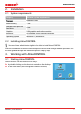
AtmoCONTROL 4.2 Simulating the programme sequence (preview) While creating the programme, you can display the prospective progression of all parameters as a diagram at any time. To do this, click on "Simulation" (Fig. 7). Depending on the complexity of the programme, it may take a few seconds for the simulation to be calculated and displayed. Fig. 7 Programme preview diagram (simulation) In simulation mode, no changes can be made to the programme, as this mode is just for information purposes.
AtmoCONTROL 4.3.3 Transferring programme via Ethernet To be able to transfer a programme via Ethernet, the appliance and computer must be connected via Ethernet, the correct IP address set (see page 10) and the appliance switched on. Click „Program"„Upload to device”. The programme is uploaded to the appliance and can be started there. 4.3.4 Transferring a programme via USB storage medium 1. Click „Program"„Export to USB drive”. The programme is saved on the USB storage medium connected. 2.
AtmoCONTROL 4.4 Programme examples For reasons of space, it is not possible to present programme examples with all the available parameters for all MEMMERT appliances here. Instead, a number of simple example programmes will be presented to familiarise you with how a programme is structured. Caution: It is important that you run through a number of programme examples to get to know AtmoCONTROL before you actually transfer and run programmes on the appliance. 4.4.
AtmoCONTROL 4.4.2 Programme example with door locking 3 4 Tolerance band 1,7 K/min 1 2 1 6 6 3 95 °C 45 °C 7 8 5 5 2 20 °C 12:00 h ≥ 0:30 h Fig. 9 The door is locked at the beginning of the programme (1). Then, the appliance heats up to 95.0 °C C (2) and maintains this temperature for 12 hours (3). Subsequently, the temperature is lowered (5) for 30 minutes (4) to 45.0 °C C and then, the door is opened (6).
AtmoCONTROL 4.4.3 Programme example sterilisation 4 6 Tolerance band 1 0% 2 3 1 100 % 100 % 0 % 6 180 °C 5 0% 2 4 7 3 20 °C 3:00 h Fig. 10 At the beginning, the fan is switched on to 100 % (1) and the air flap is closed (0 %) (2). Then, the appliance heats up to 180.0 °C C (3) and maintains this temperature for 3 hours (4). The setting „Safe“ (5) ensures that the sterilisation time does not start (6) before the set tolerance band (7) is reached and is restarted if it is exceeded.
AtmoCONTROL 4.4.4 Programme example loop 1 4 Unload 7 2 3 3 5 6 8 9 6 0% 80% 0% 80% 0% 80% 0% 80% 0% 80% 0% 80% 0% 80% 0% 80% 0% 80% 0% 80% 0% 80% 0% 250 °C 2 5 1h 1h 1 4 20 °C 1h 1h 1h 1h 1h 1h 1h 1h 1h 1h 1h 1h 1h 1h 1h 1h 1h 1h 1h 1h 8 Fig. 11 First, the appliance heats up to 250.0 °C (2) for one hour (1). Then, the fan begins to run at 80 % power (3) and the temperature is lowered for one hour (4) to 20.0 °C (5). Subsequently, the fan is switched off (6).
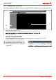
AtmoCONTROL 5. Protocol 5.1 Importing protocol from network To be able to import a protocol via network, the appliance and computer must be connected to the network, the correct IP address set (see page 10) and the appliance switched on and logged in to AtmoCONTROL. Click on the "Protocol" button (Fig. 12); the protocol data of the appliance are transferred and displayed and can be further processed – e.g. exported to a spreadsheet file format (see Section 5.3). Fig. 12 Protocol display (example) 5.
AtmoCONTROL 5.3 Exporting protocol With „Protocol"„Export”, you can export a freely definable protocol logging period into a file of the types *.csv or *.xlsx (Excel), which can be processed in spreadsheet programmes (Fig. 13). 6. Printing With the „Print" function, you can print out programmes in the editor window, as well as simulations and protocols – depending on what is currently displayed. 7. Options 7.
AtmoCONTROL 7.2.2 Use 1. Insert the USER-ID USB stick with the USER-ID file into the computer with AtmoCONTROL. 2. In the Options menu bar, click on USER-ID. 3. A window appears with the functions of the logged on appliance that can be blocked (depending on the appliance type). 4. Click on the lock icon next to the functions that should be blocked or released, and confirm this with OK. 5. Eject and remove the USER-ID USB stick, insert it in the appliance and activate.
AtmoCONTROL 7.4 Backup folder You can set up a backup folder in which AtmoCONTROL saves backup copies of programmes and user data. To do so, click on “Options””Edit Backup Folder”. You can either use the default folder or select a different one.
AtmoCONTROL 8. Event codes of the log file Log.txt (see page 12) Error codes for Generation 2012 appliances Status: October 09, 2012 In case of a hardware error of the oven, the controller displays the following error codes in a status / error window, as well as logs them in the “Log.txt” file in the “Config” directory on the SD card. The position of the error number further specifies the position of the error.
AtmoCONTROL 306: Comm Err 401: Humidity Sensor 402: Humidity Min Al 403: Humidity Max Al 404: Water tank empty 405: Temp Sensor Defunct 406: Sensor Alarm 407: Temp Min Alarm 408: Temp Max Alarm 409: Temp Auto Alarm 410: Lights Off 501: Sensor CO2 Error 502: CO2 Empty 503: CO2 Auto Switch 504: CO2 Min Alarm 505: CO2 Max Alarm 506: Sensor O2 Error 507: N2 Empty 508: O2 Min Alarm 509: O2 Max Alarm 601: Vacuum Sensor Error 602: No Shelf 603: Vacuum Min Alarm 604: Vacuum Max Alarm 700: Power Min Border 701: Dev
AtmoCONTROL Index .
AtmoCONTROL D24042 | Date 09/2014 englisch Memmert GmbH + Co. KG Willi-Memmert-Straße 90-96 | D-91186 Büchenbach Tel. +49 9122 925-0 | Fax +49 9122 14585 E-Mail: sales@memmert.com facebook.com/memmert.family Die Experten-Plattform: www.atmosafe.