OPERATING MANUAL ICH 256 Cooled incubator with compressor cooling and humidity control Optional CO2 supply or interior lighting
Manufacturer and customer service Memmert GmbH + Co. KG Willi-Memmert-Straße 90–96 D-91186 Büchenbach Deutschland Phone: +49 (0)9122 925-0 Fax: +49 (0)9122 14585 E-mail: sales@memmert.com Internet: www.memmert.com Customer service: Service hotline: +49 (0)9171 9792 911 Service fax: +49 (0)9171 9792 979 E-mail: service@memmert.com When contacting customer service, always quote the product serial number on the nameplate (see page 17). Shipping address for repairs: Memmert GmbH + Co.
About this Manual About this Manual Purpose and target group This manual describes the assembly, function, transport and operation of ICH 256 cooled incubators. It is intended for use by personnel trained by the operator, who have the task of operating and/or maintaining the cooled incubator. If you are asked to work on the cooled incubator, read this manual carefully before starting work on the unit. Familiarise yourself with the safety regulations. Only perform work that is described in this manual.
Contents Contents 1. Safety Regulations 1.1 1.2 1.3 1.4 1.5 1.6 1.7 1.8 1.9 Terms and signs used........................................................................................................... 6 Product safety and dangers ................................................................................................ 7 Safety labels .........................................................................................................................
Contents 7. Advanced Functions 7.1 7.2 7.3 7.4 7.5 7.6 7.7 7.8 Printer ............................................................................................................................... 51 Basic appliance settings (Setup) ........................................................................................ 52 Temperature monitoring .................................................................................................. 53 Communication interfaces ...............................
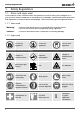
Safety Regulations 1. Safety Regulations 1.1 Terms and signs used In this manual, certain common terms and symbols are used to warn you of dangers or to give you hints that are important in avoiding injury or damage. Observe and follow these hints and regulations to avoid accidents and damage. These terms and signs are explained below. 1.1.1 Terms used "Warning" is always used whenever you or somebody else could be injured if you do not observe the accompanying safety regulation.
Safety Regulations 1.2 Product safety and dangers ICH cooled incubators are technically sophisticated, manufactured using high-quality materials and subject to many hours of testing in the factory. They contain the latest technology and comply with recognised technical safety regulations. However, there are still dangers involved, even when the appliance is used as intended. These dangers are described below. Warning! After removing covers, live parts may be exposed.
Safety Regulations 1.2.2 Additional safety regulations for cooled incubators with CO2 supply. Warning! Danger of suffocation. CO2 can have a suffocating effect in high concentrations. In normal operation, the cooled incubator gives off small amounts of CO2 to its surroundings. You should therefore ensure that the room in which it is installed is properly ventilated. Always close the stop valve or pressure reducer on the gas bottle if there is no gas bottle connected or if the bottle connected is empty.
Safety Regulations 1.
Safety Regulations 1.8 What to do in case of accidents 1. Keep calm. Act with determination and consideration. Pay attention to your own safety. 2. Switch off the cooled incubator and close the valve on the gas bottle. 3. Call a doctor. 4. Initiate first aid measures. If available: Call a trained first aid helper. In case of contact with CO2 to the eyes and skin: Rinse eyes out with water for at least 15 minutes. In case of cold burns, rinse with water for at least 15 minutes. Cover over in a sterile way.
Design and Function 2. Design and Function 2.1 Design 1 2 13 12 11 10 9 3 4 8 7 5 6 Fig.
Design and Function ► If the appliance is equipped with CO2 supply, carbon dioxide is introduced into the interior through a sterile filter. The turbulence-free interior ventilation ensures a uniform gas distribution, creating a homogeneous atmosphere. The CO2 content is reduced by introducing fresh air. ► If the cooled incubator is equipped with interior lighting, it includes an illumination box at the top of the interior (see Fig.
Design and Function 2.3 Configuration 2.3.
Design and Function 2.5 Electrical equipment ► Operating voltage: See nameplate (page 16), 50/60 Hz ► Current consumption: See nameplate (page 17) ► Protection class 1, i.e. operating insulation with PE conductor in accordance with EN ► ► ► ► ► 61010 Protection type IP 20 acc. to EN 60 529 Interference-suppressed acc.
Design and Function 2.6.2 Connection of external appliances Only appliances may be connected to external connections whose interfaces comply with the requirements for safety extra-low voltage (e.g. computer). 2.6.3 Gas connection (only for models with CO2 supply) The appliance can be connected with the supplied compressed air tube via a pressure regulator with gas bottle monitor (DIN 8546) to a CO2 compressed gas bottle or directly to a central CO2 gas supply. The primary pressure must not exceed 1.
Design and Function 2.8 EC Declaration of Conformity EC Declaration of Conformity Manufacturer’s name and address: MEMMERT GmbH + Co.
Design and Function 2.9 Designation (nameplate) The nameplate (Fig. 6) provides information about the appliance model, manufacturer and technical data. It is attached to the front of the appliance, on the right beneath the door (see page 11). 10 9 8 1 2 3 4 7 5 6 Fig. 6 Nameplate 1 Type designation 2 Operating voltage 3 Applied standard 4 Protection type 5 CE conformity 6 7 8 9 10 Address of manufacturer Disposal note Temperature range Connection/performance values Factory number 2.
Design and Function Technical data without interior lighting max. load per sliding shelve [kg] with interior lighting 30 max. load per appliance [kg] 80 Temperature Temperature recording is done by means of Pt100 in a 4-wire circuit Adjustment range normal operation: -10 °C to 60 °C, for models with CO2 supply or interior lighting 0 °C to 60 °C Adjustment precision: 0.1 °C Deviation in time: max. ±0.1 °C at 37 °C Spatial deviation: max.
Design and Function D F A E B C Fig. 7 Dimensions of ICH cooled incubators 2.11 Ambient conditions ► The cooled incubator may only be used in enclosed rooms and under the following ambient conditions: Ambient temperature: 5 ºC to 28 ºC Humidity: max. 80 % Degree of pollution: 2 Altitude of installation: max. 2000 m above sea level ► The cooled incubator may not be used in areas where there is a risk of explosions.
Delivery, Transport and Setting Up 3. Delivery, Transport and Setting Up 3.1 Safety regulations Warning! You may injure your hands or feet when transporting and setting up the cooled incubator. You should wear protective gloves and work shoes. Warning! Because of the heavy weight of the cooled incubator, you could injure yourself if you try to lift it. If possible, only transport the appliance with a forklift truck or manual pallet jack.
Delivery, Transport and Setting Up 3.3 Delivery The cooled incubator is delivered in cardboard packaging on a pallet. 3.3.1 Unpacking and checking 1. Remove cardboard packaging or cut open carefully along an edge. 2. Check the delivery note to ensure that the delivery is complete. 3. Check the inside and outside of the cooled incubator for damage.
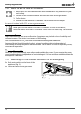
Delivery, Transport and Setting Up 3.4 Setting up ≥ 20 cm The cooled incubator may only be placed on the ground, not on a table. When doing this, ensure that the appliance is positioned exactly horizontally. The installation site must be level and must be able to reliably carry the weight of the cooled incubator (see page 17). Do not place the appliance on inflammable surfaces and do not stack. The front swivel castors can be locked with a catch.
Putting into Operation 4. Putting into Operation 4.1 Check the door and adjust if necessary See page 68. 4.2 Connecting 4.2.1 Power supply Caution: Observe the country-specific regulations when connecting (e. g. in Germany DIN VDE 0100 with residual current circuit breaker). Observe the connection and power ratings (see nameplate). The cooled incubator is intended for operation on an electrical power system with a system impedance Z max at the point of transfer (service line) of a maximum of 0.292 ohms.
Putting into Operation 4.2.4 Gas connection (only for models with CO2 supply) Warning! Danger of suffocation: CO2 can have a suffocating effect in high concentrations. In normal operation, the cooled incubator gives off small amounts of CO2 to its surroundings. You should therefore ensure that the room in which it is installed is properly ventilated. Warning! High concentrations of CO2 can cause cold burns or frostbite. Avoid contact with CO2 gas to the eyes and skin.
Operation and Control 5. Operation and Control Warning! UV light is a danger to your eyes. Your eyes could be injured by UV light if you do not wear protection. Always wear UV safety goggles when opening the door of the cooled incubator with interior UV lighting This is indicated by the warning signs on the door (refer to page 8). 5.1 Operating personnel The cooled incubator may only be operated and by persons who are of legal age and have received appropriate training.
Operation and Control 5.4 Checking interior lighting (only for corresponding model) As the light output and working life of fluorescent tubes may decline according to operational demands over time, it is necessary to check the illuminance and condition of the fluorescent tubes prior to every test. 1. For cooled incubators equipped with UV lighting: Wear UV safety goggles. 2. Switch on the interior lighting (refer to page 31) 3. Check if all fluorescent tubes are working.
Operation and Control The chamber must not be loaded too tightly, so that proper air circulation in the working chamber is guaranteed. Do not place any of the chamber load on the floor, touching the side walls or right below the ceiling (heating ribs) of the working chamber. To guarantee optimum air circulation, push in the sliding grids so that the gaps between the door, sliding grid and rear wall of the chamber are roughly the same size. Fig. 14 Correct and incorrect chamber loading 5.
Operation and Control 5.7 Basic operation The desired parameters are entered on the operating panel of the controller on the front of the appliance (Fig. 15). Basic settings, as well as those for time and pressure, can also be made here.
Operation and Control 5.8 Setting parameters Normally, all setting actions on the operating panel described on the following pages are made in the same way: 1. Select the desired parameter with the push-turn control (menu item, e. g. set temperature), then all other parameters go dark and the selected one flashes. set 2. With the SET key held down, set the desired value (e. g. 37.0 °C) with the push-turn control. 3. Release the SET key to save the set value.
Operation and Control 5.10 Setting the operating mode set set set 1. Hold down the SET key for approx. three seconds until the selected operating mode begins to flash. 2. Select the desired operating mode (normal mode, week time switch, programming mode, printer or basic appliance settings/setup by turning the control with SET key held down. 3. Release the SET key and the selected operating mode is activated. 5.10.1 Normal mode In this operating mode, the appliance runs in permanent operation.
Operation and Control UV light (only for corresponding model) Adjustment range: Off, on Daylight (only for corresponding model) Adjustment range: Off, On Both lighting modes can be combined or switched on and off independently. 5.10.2 Settings example normal mode The appliance should heat up to 37 °C with a humidity of 80 % rh and a fan speed of 40 %. The monitoring function should trigger at 38.5 °C and at 36.0 °C: For a model with CO2 supply, the CO2 content should be 5.0 %.
Operation and Control 1. Setting the normal operating mode: Hold down the SET key for approx. 3 seconds and the current operating mode then begins to flash. Select the operating mode with the push-turn control while keeping the SET key depressed. After you release the SET key, the normal operation mode is activated. SETUP PRINT 2. Setting the temperature setpoint: Hold down the SET key and set the desired temperature setpoint to 37.0 °C with the push-turn control.
Operation and Control 5. Setting the CO2 setpoint (only for models with CO2 supply) Turn the push-turn control to the right until the CO2 display flashes. Hold down the SET key and set the desired CO2 setpoint to 5.0 % with the push-turn control. Release the SET key. The appliance flashes briefly, showing the CO2 setpoint. The current CO2 actual value appears on the display and the controller begins to adjust the CO2 content to the setpoint. CO2 6.
Operation and Control By turning further to the right, parameters (temperature, humidity setpoints etc.) can be selected as in the normal operating mode. If no settings (temperature setpoint etc.) are made for the ON phase, the controller takes over the values from the normal operating mode. For reasons of safety, you should always check that a switch-on time is only programmed in the desired time blocks and days.
Operation and Control 2. Switch on Mo-Fr at 09:30 Turning the push-turn control to the left, select "Mo-Fr on" (group working days). Hold down the SET key and set the desired switch-on time with the push-turn switch to 09:30 (am). 3. Switch off Mo-Fr at 19.00 (7pm) Select "Mo-Fr off" (group working days) with the pushturn control. Hold down the SET key and set the desired switch-off time with the push-turn switch to 19.00 (7pm) 4. Switch on Sa at 10.00 (am) With the push-turn control, select "Sat on".
Operation and Control You can now select and modify the following parameters in turn (see also the adjustment example on page 34): Mo Tu We Th Fr Sa on t3 Su STERI 4 t4 t2 h off t1 IN 1 DEFRO °C 3 loop 2 1 OUT %rh mb MAX MIN AUTO SETUP PRINT IN 2 °C 4. Delayed programme start: Switch-on day Adjustment range: Monday to Sunday, workdays Mo-Fr, weekends Sa-Sun, every day Mon-Sun or no day.
Operation and Control Mo Tu We Th Fr Sa on STERI 4 t3 Su t4 t2 h off t1 DEFRO °C 3 loop 2 1 °C AUTO SETUP PRINT MAX MIN 8. Fan speed of first ramp segment Adjustment range: 10 % to 100 % in 10-% steps In the example shown: fan speed 60 % (six bars lit up) Mo Tu We Th Fr Sa on STERI 4 t3 Su t4 t2 h off t1 DEFRO °C 3 loop 2 1 °C MIN mb AUTO SETUP PRINT %rh MAX 9. Setpoint humidity (humidity to end of ramp segment) Adjustment range: 10 to 80 % rh and OFF.
Operation and Control Tu Mo We Th Fr Sa on STERI 4 t3 Su t4 t2 h off DEFRO °C 3 t1 loop 2 °C 1 MIN mb CO 2 AUTO SETUP PRINT %rh MAX 12. Daylight lighting of the first ramp segment (only for models with interior lighting for daylight and UV light) Adjustment range: on, off Each ramp must be completed with a close statement connecting the ramp to the next one.
Operation and Control 5.10.6 Close statements for ramp segments Each ramp must be completed with a close statement connecting the ramp to the next one. These commands thus control the programme sequence: NEXT Connect the next programme segment. SET-POINT WAIT (T – temperature) Wait until the setpoint temperature has been reached. The appliance starts the next programme segment only when the programmed set temperature has been reached, even if the set heating up time has already elapsed.
Operation and Control 5.10.7 Settings example programme mode On Monday at 8.00, the cooled incubator should heat up to 37 °C as quickly as possible with a fan speed of 30 %, and reach a relative humidity of 70 % rh. For models with CO2 supply, the CO2 content should be set to 5 % and for models with interior lighting, daylight should be simulated. Once the temperature and humidity have been reached, the cooled incubator should retain the setpoint values at a fan speed of 50 % for 45 minutes.
Operation and Control This ramp programme can only be set for cooled incubators equipped with CO2 supply or interior lighting. Basic appliances do not include adjustment options for CO2 or lighting. The respective descriptions in this example are therefore not relevant for these appliances. Before programming ramp sequences, especially complicated ones, it is recommended that you prepare a similar plan so that you can enter the required ramp commands correctly, as described below.
We 17 Fr Th Sa t3 Su h t2 t1 Operation and Control STERI 4 t4 DEFRO °C 3 loop 2 1 7. Setting the fan speed of the first ramp segment: PRINT Turn the push-turn control to the right untilSETUP the fan display flashes. Hold down the SET key and set the desired fan speed of 30 % (three bars lit up) with the push-turn control. MIN push on off 8. Setting the relative humidity of the first ramp segment: set card Turn the push-turn control to the right until the humidity display flashes.
Operation and Control 14. Setting the fan speed of the second ramp segment: Turn the push-turn control to the right until the fan display flashes. Hold down the SET key and set the desired fan speed of 50 % (five bars lit up) with the push-turn control. 15. Setting the relative humidity of the second ramp segment: Turn the push-turn control to the right until the humidity display flashes. Hold down the SET key and set the desired humidity setpoint to 70.0 % rh with the push-turn control. 16.
Operation and Control 21. Setting the relative humidity of the third ramp segment: Turn the push-turn control to the right until the humidity display flashes. Hold down the SET key and set the desired humidity setpoint to 50.0 % rh with the push-turn control. %rh 22. Setting the CO2 content of the second ramp segment (only for appliances with CO2 supply, otherwise please continue with point 23): Turn the push-turn control to the right until the CO2 display flashes.
Operation and Control 5.11 During operation Regularly check the water level. If necessary, add distilled water. Warning messages during operation: See page 47. CO2 mode In the heating up phase, the CO2 controller is initially deactivated. The CO2 inlet is interrupted during this period. About 5 minutes after the setpoint temperature has been reached, the CO2 control begins measuring and CO2 gas is introduced into the chamber via a sterile filter. The setpoint can be set from 0 to 20 % in 0.1 % steps.
Operation and Control Active humidity control The active humidity control guarantees that setpoint humidity is quickly reached, without the use of water trays. In the heating up phase, the humidity controller is initially deactivated. Approx. 5 minutes after the setpoint temperature is reached, the humidification and dehumidification control starts working. The setpoint can be set from 10 to 80 % rh. The humidity setpoint can also be adjusted during the transient state.
Warning Messages and Malfunctions 6. Warning Messages and Malfunctions 6.1 Warning messages The warning messages also set off an intermittent acoustic signal: This can be temporarily switched off by pressing the SET key. Error in the temperature control system (see also chapter "Temperature monitoring" on page 53): Tb active - if the temperature limiter is triggered Remedy: See page 54 hi-alarm - if overtemperature protection is triggered Remedy: Check the setting of the MAX temperature monitor.
Warning Messages and Malfunctions if the CO2 supply is defective Remedy: Set CO2 setpoint to 0, check the stop valve and connection of the gas bottle; if the gas bottle is empty, replace it and set the CO2 setpoint to the desired value. if the CO2 concentration exceeds the defined setpoint by at least 1 % for more than 3 minutes. Remedy: Open the door for 30 sec. and wait to see if the controller steadily adjusts to the setpoint. If the error occurs again, contact the customer service. 6.
Warning Messages and Malfunctions Error ... icon flashes Possible cause Remedy Temperature protection (TWW, ASF) has triggered ► Increase temperature difference between monitoring and working temperature (see page 53). ► Replace Pt100 temperature sensor of monitoring controller, if necessary (see service manual) ... and rh empty Water supply tank empty Set humidity setpoint to OFF, fill up distilled water, then reset humidity setpoint back to desired value. ...
Warning Messages and Malfunctions 6.3 Power failure In case of a power failure, the cooled incubator operates as follows: In normal and week time switch operating modes After the power supply has been restored, operation is continued with the parameters set. The time and duration of the power failure are documented in the log memory. In Programming mode ► After a power failure of less than 60 minutes, the current programme is continued from the point at which it was interrupted.
Advanced Functions 7. Advanced Functions 7.1 Printer The cooled incubator is equipped with a parallel printer port as used in computers. Standard PCL3 compatible inkjet printers with a parallel port (e.g. HP DeskJet 5550 or HP DeskJet 9xx) can be connected to the printer interface on the rear of the appliance (see page 14). Make sure that a shielded interface cable is used. The shielding must be connected to the plug casing. The controller has an internal log memory (see page 58).
Advanced Functions 7.2 Basic appliance settings (Setup) (setup options may vary depending on the appliance model) In this operating mode, the basic settings for the appliance can be made. By turning the push-turn control and holding down the SET key, the following parameters can be selected and changed, as described in chapter Basic operation on page 27: Clock time in 24 hr. format Conversion to summer time is not automatic, but must be done manually.
Advanced Functions Tolerance band ASF Adjustment range: 0.5 to 5°C (see page 53) Language Setting: GERMAN, English, franCAIS, ESPANOL and italIANO Corrective values CAL 1-3, rh20, RH80, CO2 5, CO2 10, CO2 15 for customer-side calibration of temperature, humidity and CO2 (see chapter "Calibration" on page 59) Leave setup Save all settings and leave the SETUP mode The realtime clock which is set in the SETUP contains the date and clock time. It is used for logging purposes in accordance with GLP.
Advanced Functions 7.3.1 Mechanical temperature monitoring: Temperature limiter (TB) The cooled incubator is equipped with a mechanical temperature limiter (TB) of protection class 1 in accordance with DIN 12880. If the electronic monitoring unit should fail during operation and the factory-set maximum temperature is exceeded by approx. 20 °C, the temperature limiter, as the final protective measure, switches off the heating permanently. As a warning, the icon lights up.
Advanced Functions Setting: Overtemperature protection: Adjustment range: up to max. 10 °C above nominal temperature (for details of the nominal temperature, see nameplate) Setting: 1. Select the MAX icon with the push-turn control. 2. Hold down the SET key and set the desired temperature limit with the push-turn control (e.g. to 38.5 °C).
Advanced Functions 7.3.3 Automatic temperature monitor (ASF) ASF is a monitoring device that automatically follows the set temperature setpoint within an adjustable tolerance band (Fig. 25). The ASF is activated – if switched on – automatically if the actual temperature value reaches 50 % of the set tolerance band of the setpoint (in the example: 37 °C – 1.5 °C) reached for the first time (section A). The activation of the ASF is shown by the brightly lit AUTO icon.
Advanced Functions 7.4 Communication interfaces 7.4.1 USB interface The cooled incubator is equipped by default with a USB interface. In accordance with USB specification (see Fig. 5 on page 14). With this interface, it is possible to control and log the appliance remotely from the computer. This is done with the help of the “Celsius“ software.
Advanced Functions 7.5 Log memory The controller continually logs all relevant measured values, settings and error messages at 1-minute intervals. The internal log memory is listed as a ring buffer, i e. the oldest log data is always overwritten automatically with new data. The logging function cannot be switched off and is always active. The measured data are stored in the controller, safe from manipulation.
Advanced Functions Due to this automatic defrosting, there is a minor brief increase in the chamber temperature at regular intervals. If you would like to further reduce this detraction in performance, you can decrease the defrosting frequency, e.g. to every 24 hours. In this case, please observe if there is a permanent drop in the cooling performance or a strong fluctuation of the actual value, which may be an indication that the cooling unit is icing over.
Advanced Functions For each selected balance point (Fig. 28), a positive or negative compensation correction value can be set between -2.9 ºC and +2.9 ºC. There must be a difference of at least 10 ºC between each of the individual balance points. CAL. 3 +0,3 °C CAL. 1 +0,2 °C CAL. 2 -0,4 °C ault Def tion bra cali 10°C 0° Fig. 28 20°C 30°C 40°C Temperature calibration (example) Setting: 1.
Advanced Functions 3. Set compensation correction value for CAL.2 under SETUP to - 0.4 °C: h °C °C 4. After the calibration procedure, the reference instrument should display 35 °C. 5. With CAL.1, another compensation temperature below CAL.2 can be programmed in the same way, and with CAL.3, one above this. If all compensation correction values are set to 0.0 °C, the factory calibration settings are restored. 7.8.
Advanced Functions Example: Humidity deviation at 80 % should be corrected. 1. Set humidity balance point in the SETUP to RH 80 and set the accompanying compensation correction value to 0.0 %rh: Mo Tu We Th Fr Sa t3 Su on 4 t4 t2 STERI loop IN 1 DEFRO °C 3 t1 off 2 1 OUT CO2 mb mb MAX MIN AUTO SETUP PRINT IN 2 %rh °C 2. With a calibrated reference instrument, an actual humidity of 78 % rh is measured at normal operation, with a defined setpoint humidity of 80 % rh. 3.
Advanced Functions Setting 1. Set the desired CO2 balance point in the SETUP (see page 53) and set the accompanying compensation correction value to 0.0 %. 2. With a reference instrument, measure the deviation in the stationary state in the selected CO2 balance point. 3. Under SETUP, adjust the compensation correction value. If the measured reference CO2 content is too low, the compensation correction value must be set with a negative sign. 4. Perform a control measurement with the reference instrument. 5.
Maintenance and Servicing 8. Maintenance and Servicing 8.1 Cleaning Warning! Danger of injury by electric shock. Before any cleaning work, pull out the mains plug. 8.1.1 Interior and metal surfaces Regular cleaning of the easy-to-clean interior prevents build-up of material remains that could impair the appearance and functionality of the stainless steel chamber over time.
Maintenance and Servicing 8.1.4 Cooling compressor In order to guarantee perfect function and long lifetime of the refrigeration unit, it is absolutely essential to remove dust deposits from the condenser (Fig. 33, no. 1) (with a vacuum cleaner, paintbrush or bottle brush, depending on the amount). After the screws (2) have been loosened, the air inlet cover on the front (3) can be removed and the condenser can be cleaned.
Maintenance and Servicing 8.3 Replacing fluorescent tubes (only for models with interior lighting) Caution: ► Replace the fluorescent tubes only with fluorescent tubes of the same type; e.g. UV light tubes only with UV light tubes, not daylight tubes. For information on the specifications, please refer to chapter "Technical data" on page 17. ► Do not replace single tubes, but always the entire tube set (e.g. all UV light tubes instead of just one). Replacing single tubes can influence the light output. 1.
Maintenance and Servicing 5. Unlock the plastic fixing of the tubes that need to be replaced on both sides and pull out the tubes carefully (Fig. 38). 2 1 1 2 Fig. 38 1 Remove the plastic fixing and slide to the middle. 2 Pull the tubes carefully out of the holder. 6. Insert new tubes and screw tight. 7. Attach the glass cover and fix it with the restraining plate. To do so, screw in the two Allen screws on the side again. 8. Put the illumination box back into the cooled incubator. 9.
Maintenance and Servicing 8.4 Adjusting door A well-closing door is indispensable for cooled incubators. Thanks to the combination of a chamber seal and a door seal, MEMMERT appliances optimally guarantee the tight closing of the door. In permanent operation, the flexible seal material might begin to sag. To ensure that the door closes exactly despite this, an adjustment may be necessary (Fig. 39).
Storage and Disposal 9. Storage and Disposal 9.1 Storage The cooled incubator may only be stored under the following conditions: ► in a dry and enclosed, dust-free room ► frost-free ► disconnected from the power supply and gas supply Disconnect the gas bottle and close the valve of the gas bottle. Gas bottles may be stored in closed rooms if these are sufficiently well ventilated. Disconnect the tube of the water supply tank and empty it. 9.
Index Index A D Accessories 19 Accidents 10 Acoustic signal 52 Additional fittings 13 Adjusting door 68 Air circulation 27 Alarm 52, 53, 54, 56 Alterations 9 Ambient conditions 19 Appliance error 48 Aqua dest 23 ASF 56 Automatic temperature monitor 56 Date 52 Declaration of conformity 16 Decommissioning 69 Defrosting 58 Delayed programme start 36 Delivery 20, 23 Device address 57 Dimensions 19 Disposal 69 Door 25 Door seals 65 B Basic device settings 52 Basic equipment 13 Battery water 23 C Calibratio
Index Printing out log memory 58 Product safety 7 Programme mode 29 Programme write mode 38 Protective foil 21 Pt100 temperature sensor 53 Push/turn control 25 Putting into Operation 23 Q Quick adjustment of temperature 29 R Ramps 35 Ramp segments 39 Realtime clock 53 Regular maintenance 65 Replacing fluorescent tubes 66 Responsibility of the owner 9 Ring memory 58 S Safety goggles 6, 7, 8, 9, 25, 26 Safety labels 8, 65 Safety regulations 6 Service 68 Servicing 68 Setting parameters 28, 29 Settings examp
Memmert GmbH + Co KG | PO Box 1720 | D-91107 Schwabach, Germany | Phone +49 (0) 9122-925-0 | Fax +49 (0) 9122-145-85 | E-Mail: service@memmert.com | www.memmert.com 28.06.