OPERATING INSTRUCTIONS Universal oven Steriliser Incubator UNP 200 - 800 UFP 400 - 800 SFP 400 - 800 INP 200 - 800 IFP 400 - 800
1. Contents ....................................................................................................................................... 2 2 General notes and safety notes ...................................................................................................... 4 2.1 Intended purpose when used as medical product .................................................................. 4 2.2 Transport ........................................................................................
15 Communication interface for the PC............................................................................................. 34 15.1 Communication interface RS232C ....................................................................................... 34 15.2 Bus interface RS485 ............................................................................................................ 35 16 Heating power distribution BALANCE..........................................................................
2 General notes and safety notes You have purchased a technically fully proven product which has been produced in Germany with the use of high-grade materials and the application of the latest manufacturing techniques; it has been factory tested for many hours. In addition we guarantee the supply of spare parts over 10 years.
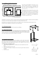
Installation facilities (accessories) The oven can be placed on the floor or on a bench (working surface). It is important that the oven is set up accurately horizontally; the door may have to be adjusted (see Section „Maintenance“) min. 20 cm 3 8 cm 8 cm 15 cm min. min. min. The spacing from the back of the oven to the wall should be at least 15 cm. The spacing to the ceiling must not be less than 20 cm and that at the side to the wall not less than 8 cm.
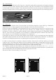
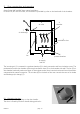
3.4 Initial start-up When the oven is started up for the first time, it should be supervised continuously until steady conditions have been reached. Severe vibrations during transport may cause movement of the temperature probes in their holder inside the chamber. Note therefore that before the first start-up the temperature probes should be checked for their correct position and, if necessary, carefully aligned in their mounting (see ill). Ill: Chamber ceiling with Pt 100 metal temperature probes 3.
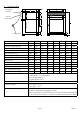
4 Technical data connection RS232C printer connection supply plug Model Chamber width A [mm] Chamber height B [mm] Chamber depth C [mm] Oven width D [mm] Oven height E [mm] Oven depth F [mm] Chamber volume [litre] Weight [kg] Power, ovens UNP/UFP/SFP [W] Power, ovens INP/IFP [W] Max. number of shelves Max. load per shelf [kg] Max.
4.
WARNING! Always pull out the supply plug before opening the oven cover! 4.3 • • • • • • • • Electrical equipment Operating voltage see label 50/60 Hz Current rating see label Protection Class 1, i.e.
5 Oven construction and operation Ovens Series UNP and INP have natural ventilation. In Series UFP, SFP and IFP ovens, air circulation is provided by a fan on the back wall of the chamber. 6 air valve 4 chamber 7 air discharge 3 ventilation slots 5 fan 1 air supply fresh air 2 preheat chamber The incoming air (1) is warmed in a preheat chamber (2) in both convection and fan-circulation ovens. The preheated air enters the chamber (4) through ventilation slots (3) in the chamber side wall.
5.2 Controls and indications time display Mo Tu We heating operating mode indication Th Fr on Sa t3 Su h off temperature display STERI 4 t4 t2 loop IN 1 DEFRO °C 3 t1 alarm indication 2 set text display SET key push/turn control (main switch) mb IN 1 IN 2 OUT CO2 mb MAX MIN AUTO SETUP on off OUT %rh °C 1 PRINT IN 2 push card Ill.: UFP500 air valve indication monitor temperature indication fan indication chip card reader 5.
6 Selecting the operating mode PRINT Normal operation Weekly programmer Programme operation SETUP Printer Basic settings After holding down the SET key (approx. 3 sec), the current operating mode flashes on the display. A different operating mode can be selected with the push/turn control while the SET key is being held down. After the SET key has been released the controller operates in the new operating mode.
8 Normal operation PRINT SETUP In this operating mode the oven operates continuously. The settings for operating the oven can be selected. The settings act directly on the operation of the oven. °C MAX MIN AUTO By rotating the push/turn control the following parameters can be selected and can be altered as described in the Section „Setting the parameters“: Temperature setpoint Range: 20 °C up to nominal temperature (details see label) ˚C Fan speed Range: 0 to 100% in 10% steps.
Setting example “Normal operation“ The oven (UFP500) has to heat up to 180°C at 50% fan speed and with the air valve 20% open. The monitor function has to operate at 200°C. °C monitor temperature 200°C 180°C h 1. Select operating mode “Normal operation“ PRINT After holding down the SET key (approx. 3 sec), the current operating mode is flashing. Select operating mode I with the push/turn control while holding down the SET key. After the SET key has been released the controller is in operating mode I.
9 Weekly programmer PRINT SETUP In this operating mode the weekly programmer is activated and the oven switches on and off automatically at the programmed times. While the weekly programmer is in the OFF phase the oven is in standby mode. Heating and fan are switched off, the controller display is dimmed and shows the clock time. The sequence of the weekly programmer is repeated every week. A maximum of 9 time blocks, each consisting of ON time and OFF time, can be programmed.
Su Sa Fr Th We Tu Mo Programming example “Weekly programmer“ The oven (UFP500) has to switch on at 07.30 hrs from Mo to Fr (workday group) and switch off at 18.00 hrs. In addition it has to operate on Saturday from 10.00 to 14.00 hrs. 1. Select operating mode “Weekly programmer“ PRINT After holding down the SET key (approx. 3 sec) the current operating mode is flashing. Select operating mode “Weekly programmer“ with the push/turn control while holding down the SET key.
10 Programme operation PRINT SETUP In this operating mode, up to 40 freely programmable temperature-time ramps can be set.
Mo Tu We Th Fr Sa on t4 t2 h off t3 Su t1 loop °C °C MAX SETUP PRINT Duration of first ramp segment Range: 1 minute to 999 hours.
10.1 Closure commands for ramp segments NEXT Follow-on with next programme segment. SPWT (T) Wait until the setpoint temperature is reached. The oven only starts the next programme segment when the programmed setpoint temperature has been reached, even if the programmed heating time has already elapsed. SET-POINT WAIT LOOP Ramp repeat function. The set programme is repeated after passing through all programmed segments.
Programming example programme operation The oven (UFP500) has to heat up as quickly as possible to 180°C on Monday at 08.00 hrs with a fan speed of 50% and the air valve open 20%. The oven has to hold this temperature for 45 minutes with the air valve 50% open, followed by cooling down in one hour to 60°C with fan switched off and the air valve open 20%. ˚C 250˚C 200˚C 0:45h 100˚C Mo 8:00h 150˚C 1:00h 50˚C t=time 0˚C 1. Select operating mode “programme“ PRINT After holding down the SET key (approx.
5. Select duration of first ramp segment Turn the push/turn control further clockwise until the time of the first ramp segment is flashing. Hold down the SET key and set the time 00:01 using the push/turn control. h 6. Select temperature of first ramp segment Turn the push/turn control clockwise until the temperature display is flashing. Hold down the SET key and set the required temperature setpoint of 180 °C using the push/turn control. ˚C 7.
14. Set closure command for second ramp segment Turn the push/turn control clockwise until a segment closure command (e.g end ) appears. Hold down the SET key and set next with the push/turn control. 15. Select duration of third ramp segment Using the push/turn control select the time indication Hold down the SET key and set the time 08:00 using the push/turn control. h 16. Select temperature of third ramp segment Turn the push/turn control clockwise until the temperature display is flashing.
11 Printer PRINT PRINT SETUP All PERFECT ovens are fitted as standard with a parallel printer interface, as used on personal computers. This parallel printer interface on the back of the oven is suitable for connecting conventional PCL3compatible ink jet printers which are provided with a parallel printer interface (e.g. HP Deskjet 5550 or HP Deskjet 9xx). It is important to use a screened interface cable. The screen must be connected to the plug case.
12 Basic oven settings SETUP PRINT SETUP In this operating mode it is possible to make the basic settings of the oven. Clock time, date, day, year, and settings of sounder, of address assignment, monitoring units, heater power and calibration are set here.
Heater power reduction for gentle heating of the load and reduction of the mean current taken from the power supply. Note: reduction in heater power may lead to high temperatures no longer being achieved. Range: 50 to 100% Tolerance margin ASF Range: Universal ovens Uxx 2 to 20 Sterilisers Sxx 2 to 20 Incubator Ixx 0.5 to 5 (see Section „Temperature monitor”) Temperature monitor function Adjustable temperature monitor (TWW) Protection Class 3.
13 Temperature monitor and protection devices The monitor temperature is measured with a separate PT100 temperature sensor inside the chamber. The monitor unit provides protection for the oven load as well as protection for oven and its surroundings. The oven is provided with duplicate overtemperature protection (mechanical / electronic) according to DIN 12 880.
13.2 Electronic temperature monitor 13.2.1 Overtemperature protection MAX Range: up to 10°C max above nominal temperature (for nominal temperature see label) ˚C MAX MIN AUTO 13.2.2 Undertemperature protection MIN Range: from 10°C below minimum temperature of oven to 10°C above nominal temperature of oven (for nominal temperature see label). Using the push/turn control select the symbol MAX -Symbol anwählen. Hold down the SET key and set the protection temperature using the push/turn control.
The manually set monitor temperature and the electronic overtemperature protection are monitored on PERFECT incubators by an adjustable temperature monitor (TWW) Protection Class 3.1 to DIN 12 880, or by an adjustable temperature limiter (TWB) Protection Class 2 to DIN 12 880. The choice of temperature monitor is selected in SETUP (see the menu item Tolerance margin ASF in Section „Basic oven settings”) 13.2.3 Adjustable temperature monitor (TWW) Protection Class 3.
13.2.5 Automatic temperature monitor (ASF) AUTO A monitoring device which automatically follows the selected temperature setpoint. The tolerance margin of the ASF is set in SETUP (see the menu item Tolerance margin ASF in the Section „Basic oven settings SETUP“). Automatic temperature monitor Using the push/turn control select the AUTO OFF symbol. °C Hold down the SET key and select off using (ASF OFF) the push/turn control.
Going outside tolerance margin = ASF alarm Going outside the selected tolerance margin of the setpoint (in the example 150°C +/-10°C), for example through opening the oven door during operation, triggers the alarm. -symbol. Triggering the ASF alarm is indicated by flashing AUTO and If the sounder is switched on in SETUP, the ASF alarm is additionally signalled by an interrupted tone. By pressing the SET key the sounder can be switched off temporarily until the next occurrence of an alarm event.
Setpoint changed = ASF de-activated automatically If the temperature setpoint is altered, the automatic temperature monitor is automatically de-activated temporarily (see in the example the setpoint is changed from 150°C to 75°C) until the tolerance margin of the new temperature setpoint is reached (see in the example below: the ASF is re-activated at 75°C +/10°C).
14 Calibration User-calibration of oven and controller, with three calibration temperatures selected by the user. CAL1 temperature calibration at low temperature CAL2 temperature calibration at medium temperature CAL3 temperature calibration at high temperature Either a positive or a negative calibration correction can be applied to each selected calibration point. General calibration instructions: 1. 2. 3. 4. 5.
Note: If all calibration corrections are set to 0.0°C the factory calibration is restored. Calibration point 1 Calibration temperature Range down to 10°C below CAL2 h Calibration point 2 Calibration correction Range –4.9°C to +4.9°C ˚C Calibration temperature Range 10°C above CAL1 to 10°C below CAL3 h Calibration point 3 Calibration correction Range –4.9°C to +4.
15 Communication interface for the PC 15.1 Communication interface RS232C The oven is provided as standard with a serial communication interface RS232C according to DIN 12 900-1. Using this interface it is possible to control the oven from the PC and to produce reports. This is done using the “Celsius“ software. For this purpose the oven has to be assigned a unique device address in sub-menu SETUP, option ADDRESS; This is the address through which the PC communicates with the oven.
15.2 Bus interface RS485 When so ordered, the oven can be equipped at the factory with an RS485 interface instead of the RS232C interface. This permits networking of several ovens (up to 16) with a single PC using a common 2-wire circuit. The system is operated using the “Celsius” software. A unique device address has to be assigned to the oven in sub-menu SETUP, option ADDRESS. This is the address through which the PC communicates with the oven. The default setting is ADDRess 0.
16 Heating power distribution BALANCE On ovens series INP 500-800 and UNP/UFP 400-800 it is possible in SETUP to correct the heating power distribution BALANCE between the top and bottom heater groups to suit the individual application. The adjustment range is –50% to +50%. The setting 0% restores the factory-set heating power distribution.
17 Report memory The controller continuously records all relevant measurements, settings and error messages at 1-minute intervals. The internal report memory is arranged as a ring memory, i.e. the new data always overwrite the oldest report data. The report function can not be switched off but remains active at all times. The data are stored in the controller, protected against any manipulation. The controller memory can be read to produce documentation. Every data set is stored with a unique date stamp.
18 Memory card: MEMoryCard XL A temperature programme with up to 40 ramps can be programmed on the MEMoryCard XL. Programming can take place directly on the controller or through the PC program “Celsius”. For improved clarity it is recommended that extensive programmes are prepared graphically on the PC. Where a MEMoryCard XL is programmed, it can be read only on the same oven type for which it has been programmed.
Note: The programme remains stored on the Memory Card XL after the card has been removed from the unit. It can however be overwritten at any time by the PC using “Celsius”. Details on programming the MEMoryCard XL with PC and „Celsius“ can be found in the „Celsius“ Operating Manual and in the Online Help. 18.4 Documentation on memory card MEMoryCard XL The actual temperatures can be documented continuously on the memory card while the programme is running from the chip card.
19 Sterilisation chip card (for INP incubators only) Sterilisation Parameter: 160 °C / 4:00 h Unit-ID: ________________________ Sterilisation Process Control Card The STERICard starts an automatic and preset sterilisation process. The automatic sterilisation process starts as soon as the STERICard is inserted into the oven and started by the user.
20 User-ID-Card (available as optional extra) Name: _____________________ ID: _____________________ access authority card The User-ID-Card stores the serial number of the oven and a unique user number in encrypted format. The User-ID-Card therefore functions only in the oven with the corresponding serial number. Each log-on via the User-ID-Card is documented in the internal flash memory. If the User-ID-Card is inserted, the SETUP menu includes the additional item ID-LOCK.
21 Sterilisers 21.1 Purpose definition for MEMMERT hot air sterilisers The oven SFP is intended for the sterilisation of medical materials by dry heat using hot air at atmospheric pressure. 21.2 Notes in accordance with Medical Products Guidelines For sterilisers in the context of the Law on Medical Products (MPG), the „Celsius“ software may only be used for logging purposes, but not for the remote control (remote operation) of devices. The product lifetime specified by the manufacturer is 8 years. 21.
The following table gives typical values for the holding time to be set, with different amounts of load, for sterilisers with and without fan. Please note that these values can be employed only with correct and loose distribution of the load. Notes on the correct loading of the steriliser can be found in these Operating Instructions and also on the label affixed to the steriliser.
Programming example steriliser The steriliser (SFP600) has to sterilise at a temperature of 180°C and a medium quantity of load for one hour and 30 minutes. By setting a cooling time the load can only be removed after it has cooled down. °C heating time sterilisation time cooling time 180°C t=time 1. Select operating mode “Programme“ After holding down the SET key (approx. 3 sec) the current operating mode is flashing.
7. Set air valve for first ramp segment Turn the push/turn control clockwise until the air valve symbol is flashing. Hold down the SET key and set the air valve to 20% using the push/turn control. The air valve can be open for drying during heating. 8. Set closure command of first ramp segment Turn the push/turn control clockwise until a segment closure command (e.g.end ) appears. The segment closure command Hold down the SET key and set SPWT [T] with the push/turn control.
14. Select duration of third ramp segment Using the push/turn control select the time indication Hold down the SET key and set the time 00:01 using the push/turn control h 15. Select temperature of third ramp segment Turn the push/turn control clockwise until the temperature display is flashing. Hold down the SET key and set the required temperature setpoint of 30 °C using the push/turn control. ˚C 16.
22. Set air valve for fourth ramp segment Turn the push/turn control clockwise until the air valve symbol is flashing. Hold down the SET key and set the air valve to 0% using the push/turn control. The air valve is closed after sterilisation. 23. Set closure command for fourth ramp segment Turn the push/turn control clockwise until a segment closure command (e.g. end ) appears. Turn the push/turn control clockwise until End appears on the display and press the SET key briefly to enter.
22 Cleaning Regular cleaning of the easy-to-clean inside of the chamber prevents deposits which over time can detract from the appearance and the functionality of the stainless steel chamber . The metal surfaces of the oven can be cleaned with commercially available cleaning agents for stainless steel. It is important to ensure that no rust-forming object comes into contact with the chamber or the stainless steel casing. Rust deposits cause infection of the stainless steel.
24 Error messages E-0 E-1 E-2 E-3 E-L1 E-L2 E-L3 E-LA Error on self test Power module triac faulty Power module faulty PT100 temperature probe faulty Error communication to power unit L1 Error communication to power unit L2 Error communication to power unit L3 Error communication to all power units (possibly controller faulty) As far as PERFECT appliances are concerned, error messages are shown in the alphanumeric display.
26 CE Conformity Declaration EC Declaration of Conformity Manufacturer´s name and address: MEMMERT GmbH + Co. KG Äußere Rittersbacher Straße 38 D-91126 Schwabach Universal oven UNB … / UFB … / UNE ...
EC Declaration of Conformity Manufacturer´s name and address: MEMMERT GmbH + Co. KG Äußere Rittersbacher Straße 38 D-91126 Schwabach Incubators INB … /INE … / INP … / IFE ... / IFP ...
EC Declaration of Conformity Manufacturer´s name and address: Product: Type: Sizes: Nominal voltage: MEMMERT GmbH + Co.
Standard ovens (UNP / UFP / INP) are safety-approved and bear the test marks: Sterilisers (SFP) are safety-approved and bear the test marks: 1275 This product is subject to the Directive 2002/96/EC by the European Parliament and the EU Council of Ministers which concerns Waste Electrical and Electronic Equipment (WEEE). This product has been put on the market after 13 August 2005 in countries which have already incorporated this Directive into National Law.
28 Index A H R accessories 9 address 53 air supply 10 air valve 13 air valve indication 11 alarm indication 11 alarm symbol 26, 28 ASF 29 automatic temperature monitor 29 heating power distribution 36 HOLD 19 ramp segments 19 RS232C 34 RS485 35 B BALANCE 36 basic oven settings 24 bus interface 35 C calibration 32 calibration correction 32 calibration temperature 32 CE conformity declaration 50 cleaning 48 closure commands 19 connection 8 construction, oven 10 controls 11 customer service 53 D day gr
page 55 PERFECT
Memmert GmbH + Co. KG | Postfach 1720 | D-91107 Schwabach | Tel. +49 (0) 9122 / 925 - 0 | Fax +49 (0) 9122 / 145 85 | E-Mail: service@memmert.com | www.memmert.com 08.11.