Operating Instructions Self Drying Vacuumpump PM 200
INNOVATIVE TECHNOLOGY WORLDWIDE Operating Instructions PM 16633-842.3 Self Drying Pumps Laboratory Vacuum Pumps with Drying System PM 16633-842.3 You have selected a high-quality KNF product; the following tips will help you operate it safely, and reliably over a long period of time. Carefully study operating instructions before using the pumps and observe at all times the relevant instructions to avoid dangerous situations. 0. List of Contents 1. Description, Operating Conditions 2. Safety 3.
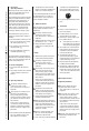
KNF resrve the right to make changes 1. Description, Operating Conditions The pumps transfer, and evacuate 100 % oil-free. In operation they are gastight, and maintenance-free. The self drying pumps make it possible during evacuation to blow the condensed liquid out of the pump heads at high speed, while maintaining the vacuum in the recipient at a constant level. After drying the pump heads the pumps achieve a greatly improved vacuum and evacuate much faster than pumps without a drying system.
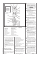
Valve voltage 24 V DC blue (-) for tube ID 10 brown (+) 231 Mains switch Fig. 1: Pump PM 16633-842.3-3.00 The pumps must not start against pressure. This also applies when the pump restarts after the power has been cut off for a short period. The components to be connected to the pump must be designed to withstand the pneumatic data of the pumps (see Section 8). The maximum permissible operating pressure (1 bar g) must not be exceeded.
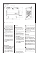
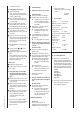
Orientation of disk springs Pump N 842_ has a round shape of head Specification Screw (12x) Screw (3x) Disk spring Top plate Head plate Valve plate/sealing Intermediate plate Guide pin Structured diaphragm Spacer (thick) Spacer (thin) Dampening ring A Screw Dampening felt Dampening ring B Adapter Dampening ring C Dampening diaphragm PM 1633-842.3-3.
second pump head. 6. e.) Refitting the pump heads At one pump head: Press the lip on the edge of the structured diaphragm into the groove in the housing. Place the intermediate plate , with the valve plates/sealings on the adapter . Place the head plate on the intermediate plate in the position indicated by the guide pin . Place the top plate on the head plate in the right position. Gently tighten screws in diagonal order.
Appendix: Customer statement for repair order (sample statement for copying) In order for KNF to repair the pump, the customer must provide a statement on the media which were pumped and on pump cleaning. Please fill out the corresponding KNF form, and submit it together with the pump. Statement/Certificate We confirm that the pump model listed below (please specify) ............................................. ............................................. .............................................
english 25.11.