
Owner manual


nents before servicing.
2.) Ensure that the service personnel
is not subject to a health hazard.
Apply the safety and protection
measures that are necessary for
the medium that has been handled
by the pump (example: the use of
protective gloves).
3.) Ensure that discarded parts and
materials are safely and correctly
disposed of.
Use only original KNF replacement
parts.
Required tools and material:
Service Set (see section 7)
Philips-head screwdriver No. 2.
Change the structured diaphragms and
valve plates/sealings in the following
sequence:
a.) Preparatory steps
b.) Remove pump heads
c.) Change structured diaphragms
d.) Change valve plates/sealings
e.) Refit pump heads
f.) Final steps.
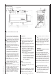
The postion numbers in the fol-
lowing text refer to fig. 2.
a.) Preparatory Steps
Shut down system (see section 4.2)
including disconnecting the pump
from the power source (pull out
plug of electrical supply unit).
Remove tubing from the inlet and
outlet connectors of the pump.
b.) Removing the pump heads
On the pneumatic head connec-
tions, loosen one of the union nuts
by hand. Then slightly loosen the
angle-fitting in the pump head by
turning it anticlockwise
, so that the
connecting tube can be pulled out.
Loosen the outer screws on
eachpump head.
Carefully remove both pump heads
(top plate , head plate and
intermediate plate ).
The soleonid valve of the
drying system remains fitted
in this situation.
c.) Change structured diaphragms
Push down one structured dia-
phragm until other diaphragm is
pushed upwards to its highest
position.
Carefully unscrew the higher
strucutred diaphragm anti-clock
wise using both hands.
Replace all spacers / onto the
screw thread of the new structu-
red diaphragm (same number and
order)
Screw in the new structured dia-
phragm and tighten it by hand;
you do not need any tool.
Change the second structured dia-
phragm as described above (step
to ) for the first.
Changing the two diaphragms one
after the other ensures that the
same number of diaphragm spa-
cers are refitted as were removed.
This is essential to maintain the
pneumatic performance of the
pump.
d.) Change valve plates/sealings
Unscrew the three screws in
the top plate of one pump head.
Carefully remove top plate and
head plate from intermediate
plate ; exposing the valve pla-
tes/sealings .
Remove old valve plates/sealings
.
If there should be deposits in the
recesses in the intermediate plate
, clean them until the deposits
have been completly removed.
Insert new valve plates/sealings
in the recesses in the interme-
diate plate (upper and lower
sides of the valve plates/sealings
are identical).
Carry out the steps to for the
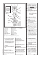
PM 1633-842.3-3.00 e 11/05
4
Specification
Screw (12x)
Screw (3x)
Disk spring
Top plate
Head plate
Valve plate/sealing
Intermediate plate
Guide pin
Structured diaphragm
Spacer (thick)
Spacer (thin)
Dampening ring A
Screw
Dampening felt
Dampening ring B
Adapter
Dampening ring C
Dampening
diaphragm
Orientation of disk
springs
Fig. 2: Pump head for N 842.3_ (exploded drawing, symbolic)
Pump N 842_ has a round shape of head