AT3515 3.5” Bulldog 3.5” IDE Solid State Flash Drive User Guide 80-03-00037 Revision 1.1 April 2006 Memtech SSD Corporation 2107 N. First Street, Suite 415 San Jose, CA 95131 (408) 452-1277 (800)445-5511 www.memtech.
Table of Contents 1. HIGHLIGHTS ........................................................................................................... 3 2. INTRODUCTION ...................................................................................................... 3 3. INSTALLATION ....................................................................................................... 4 3.1 PROCEDURE .........................................................................................................
1. HIGHLIGHTS • • • • • • • • • • • • 128 Mbyte to 8 Gbyte uncompressed capacity Full -40oC to +85oC operating temperature range 5 volt, low power operation Completely solid state - no moving parts and no batteries Extremely Rugged - 1000G operating shock, 15G operating vibration 3.5” drive form factor with a 40-pin, 0.1in standard IDE interface 72-bit Reed-Solomon ECC for exceptional data reliability Power hold-up circuit 0.
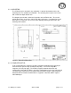
3. INSTALLATION 3.1 PROCEDURE 3.1.1 ESD PRECAUTIONS Static electricity kills... electronics! Before handling the AT3515, please observe the following precautions to avoid ESD damage to the unit: • • • Keep the drive in its shielded bag until ready to install. Ground yourself by touching a grounded chassis frame of the computer, or use a grounded wrist strap before and during the installation process. Do not touch the exposed drive electronics or connectors.
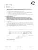
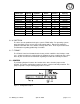
3.1.4 MOUNTING The AT3515 may be mounted in any orientation. A total of four bottom and six side mounting holes are available for installation. The mounting holes require 6-32 screws with a maximum depth of 0.25 inch. The diagram given below is valid for all capacities of the AT3515 drive. The overall outside dimensions are 4 inches (101.6 mm) wide, 5.56 inches (141.22mm) long, and 0.473 inches (12 mm) tall. Please refer to the following drawing for dimensions and mounting-hole locations.
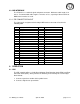
Drive Type AT3515-128 AT3515-256 AT3515-384 AT3515-512 AT3515-768 AT3515-1024 AT3515-2048 AT3515-3072 AT3515-4096 AT3515-6144 AT3515-8192 Physical Capacity 128 MB 256 MB 384 MB 512 MB 768 MB 1024 MB 2048 MB 3072MB 4096MB 6144MB 8192MB Cylinders 977 980 745 993 1489 1986 3969 5953 7937 11628 15504 Heads 8 16 16 16 16 16 16 16 16 16 16 Sectors 32 32 63 63 63 63 63 63 63 63 63 Available Capacity 122 MB 245 MB 366 MB 489 MB 732 MB 977 MB 1953MB 2930 MB 3906.5 MB 5723.2 MB 7630.9 MB 3.1.
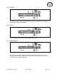
3.2.1 MASTER The drive is configured as a master device if no jumper is installed or if the jumper is installed on the master jumper block. 3.2.2 SLAVE The slave jumper allows the drive to be configured as a slave. 3.2.3 CABLE SELECT The Cable Select jumper allows the drive to be configured as a master or slave as determined by the drive’s position on an IDE cable. A maximum of two drives may be connected to one standard IDE cable. 3.
3.2.4 WRITE PROTECT The Write Protect jumper prevents data from being written to the drive. 3.2.5 FACTORY DEFAULT The factory default configuration is master. No jumpers are installed. 3.
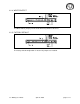
3.3 IDE INTERFACE The AT3515 uses a unitized signal and power connector. Maximum cable length is 18 inches. Recommended cable length is 12 inches or less, especially if advanced PIO or DMA transfer modes are used. 3.3.1 IDE CONNECTOR PINOUT The signal to pin assignment for the 40-pin IDE interface connector is listed in the following table.
4.2 MTBF The MTBF can be logically calculated in hours using the following formula. # Flash Chips * # Blocks *Re-programming Cycles * Area Rate MTBF = -----------------------------------------------------------------------------------Average Programming Sectors per hour (1 sector = 512 bytes) Note: The program area is the area that is not changed once it has been programmed. The remainder of the drive is thus considered “Reprogrammable”.
4.3.3 POWER ROUTING Bad power can lead to bad data. To avoid “glitches” or noise on the Vcc and ground lines, power in the system should be routed so that all peripherals are sourced from the power supply in a star configuration, as opposed to routing a single continuous supply line to each device in the system. Routing power in the star configuration, as is done on most desktop PCs, will minimize the effect on one device’s current draw on another device.
6. SPECIFICATIONS 6.1 INTERFACE IDE Compatibility IDE Drive Number Physical Capacity Physical Sector Size ATA-3 compliant Drive 0 or 1 128 Mbytes to 8 Gbytes 512 bytes 6.2 PERFORMANCE Average Access Track/Track Access Sequential Read Sequential Write Random Read Random Write Weighted Average 0.3 ms 0.3 ms 6 Mbytes/sec sustained 6 Mbytes/sec sustained 6 Mbytes/sec sustained 6 Mbytes/sec sustained 6 Mbytes/sec 6.
7. APPENDIX 7.1 CONTACT INFORMATION For Technical Support or Warranty Repair information, please contact Memtech at: Memtech SSD Corporation 2107 N. First Street, Suite 415 San Jose, CA 95131 phone: (408) 452-1277 or (800) 445-5511 fax: (408) 452-7936 7.2 ATA SPECIFICATION INFORMATION Information regarding the ATA-3 specification may be obtained from the following locations: AT-Attachment Document Distribution Global Engineering 15 Inverness Way East Englewood, Co.