SC35 Mastodon 3.5” Solid State SCSI Drive User Guide 153205-001 Revision 4.8 July 30, 2002 Memtech SSD Corporation 7628 Las Positas Road Livermore, CA 94550 (800)445-5511 www.memtech.
Table Of Contents 1. HIGHLIGHTS 3 2. INTRODUCTION 3 GENERAL DESCRIPTION 4 3. 3.1 3.2 4. 5. 19 INSTALLATION 20 20 20 21 21 22 Switch Locations SCSI ID Selection Write Protection Termination Jumper Definitions Memory Size 22 23 23 23 23 23 TROUBLE SHOOTING GUIDE 7.1 7.2 7.3 7.4 8. Default Configuration Hardware Installation Procedure Power and Cable Attachments Software Installation Procedure JUMPER CONFIGURATION 6.1 6.2 6.3 6.4 6.5 6.6 7. 4 5 GENERAL SPECIFICATIONS 5.1 5.2 5.3 5.4 6.
1. HIGHLIGHTS • • • • • • • • • • • • • • • • 27648 Mbyte uncompressed capacity Full -40oC to +85oC operating temp range Active Remap™ Wear Leveling Technology Unmatched SCSI-II compatibility On-board active termination 5 volt, low power operation Completely solid state - no moving parts 500G operating shock 10G operating vibration Rugged, 3.5” half height drive formfactor Single-ended 50 pin SCSI interface 0.7 millisecond random access time 1.
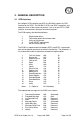
3. GENERAL DESCRIPTION 3.1 SCSI Interface An intelligent SCSI controller from NCR, the 53C90A, handles the SCSI interface for the SC35. The 53C90A is SCSI-I and SCSI II compliant, and automates much of the interface overhead. It has a 16 byte FIFO, a DMA interface, and numerous command and control registers. The SC35 employs the following attributes: 1. 2. 3. 4. 5.
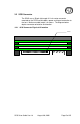
3.2 SCSI Connector The SC35 uses a 50-pin right angle 0.1 inch center connector mounted on the PCB to create both a power and signal connection to the host. Maximum cable length is 6 meters. The diagram below depicts connector orientation and location. 3.2.1 SCSI Connector Physical Orientation Pin #1 SC35 User Guide Ver 4.
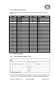
3.2.2 SCSi Connector Pinout The following shows the pin connections for the SCSI connector used on the SC35.
appropriate medium-access command without returning CHECK CONDITION status, this command shall return a GOOD status. If the logical unit cannot become operational or is in a state such that an initiator action is required to make the unit ready, the target shall return CHECK CONDITION status with a sense key of NOT READY. 3.3.2 Rezero Unit Command – 01h Rezero Unit CDB The REZERO UNIT command requests that the target set the logical unit to a specific state.
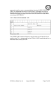
3.3.3 Request Sense Command – 03h Request Sense CDB The REQUEST SENSE command requests that the SC35 transfer sense data to the initiator. If the SC35 has no sense data available to return, it will return a sense key of NO SENSE and an additional sense code of NO ADDITIONAL SENSE INFORMATION. The sense data shall be preserved by the target for the initiator until retrieved by a REQUEST SENSE command or until the receipt of any other I/O process for the same I_T_x nexus.
Sense data format SC35 User Guide Ver 4.
3.3.4 Format Unit Command – 04h The FORMAT UNIT command formats the medium into initiator addressable logical blocks per the initiator-defined options. In addition, the medium may be certified and control structures may be created for the management of the medium and defects. Format Unit CDB Only the simplest and mandatory forms of the FORMAT UNIT command (with no format data) are implemented on the SC35. This routine accomplishes medium formatting with little initiator control over defect management.
3.3.5 Read (6) Command – 08h The READ (6) command requests that the SC35 transfer data to the initiator. The most recent data value written in the addressed logical block shall be returned. Read (6) CDB The logical block address field specifies the logical block at which the read operation shall begin. The transfer length field specifies the number of contiguous logical blocks of data to be transferred. A transfer length of zero indicates that 256 logical blocks shall be transferred.
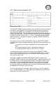
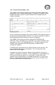
3.3.7 Inquiry Command – 12h The INQUIRY command requests that information regarding parameters of the SC35 be sent to the initiator. Inquiry CDB An enable vital product data (EVPD) bit of one specifies that the SC35 return the optional vital product data specified by the page code field. If any optional fields in the CDB are set that the SC35 does not support, it will return a CHECK CONDITION status with the sense key set to ILLEGAL REQUEST and an additional sense code of INVALID FIELD IN CDB.
Standard Inquiry Data Format Please refer to the SCSI specification for further details on the vital product data pages and formats. SC35 User Guide Ver 4.
3.3.8 Reserve Unit – 16h The RESERVE command is used to reserve a logical unit or, if the extent reservation option is implemented, extents within a logical unit. Reserve CDB 3.3.9 Release Unit – 17h The RELEASE command is used to release a previously reserved logical unit, or, if the extent release option is implemented, to release previously reserved extents within a logical unit. Release CDB SC35 User Guide Ver 4.
3.3.10 Mode Sense The MODE SENSE (6) command provides a means for a target to report parameters to the initiator. It is a complementary command to the MODE SELECT (6) command. Mode Sense CDB A disable block descriptors (DBD) bit of zero indicates that the target may return zero or more block descriptors in the returned MODE SENSE data, at the target’s discretion. A DBD bit of one specifies that the target shall not return any block descriptors in the returned MODE SENSE data.
3.3.12 Read Capacity – 25h The READ CAPACITY command provides a means for the initiator to request information regarding the capacity of the logical unit. Read Capacity CDB 3.3.13 Extended Read (10) – 28h The READ (10) command requests that the target transfer data to the initiator. The most recent data value written in the addressed logical block is returned. Read (10) CDB SC35 User Guide Ver 4.
3.3.14 Extended Write (10) The WRITE (10) command requests that the SC35 write the data transferred by the initiator to the medium. Write (10) CDB SC35 User Guide Ver 4.
3.3.15 Erase Command Erase CDB The ERASE (10) command requests that the target erase the specified number of blocks starting at the specified logical block address on the medium. As used here, erased means the medium shall be erased. The previous data recorded on the medium, if any, shall not be recoverable. The Remap Table is retained, thus allowing write and read access to the memory. The erase all (ERA) bit set to one indicates that all blocks on the medium shall be erased.
4. GENERAL SPECIFICATIONS Interface SCSI Compatibility SCSI Device Type Maximum Capacity Bytes/Block Bus Width Termination ANSI X3.131-1994 0 - Direct Access Device 27648 Mbytes 512 8 bits Active – on board Data Transfer Specifications Bus width Read Transfer Rate Write Transfer Rate Data Access time 1 byte (8 bits) 1.5 Mbyte/sec., sustained 650 Kbytes/sec sustained 0.
5. INSTALLATION 5.1 Default Configuration The default jumper switch configuration is given below. Always power down the unit before changing the SCSI ID or write protect switches. Changing these settings with power applied may result in the changes not being recognized. New with this revision is the addition of a jumper block on the front of the drive. Please refer to the diagram below for the location of the block.
5.2.8 Make sure that pin one on the cable, on the SCSI controller and on the SC35 are correctly aligned. The SC35 uses a square pad on the connector to indicate pin one, and most cables are marked with a triangle on the connector or a stripe on the cable itself to indicate the first pin. 5.2.9 Attach the power cable from the system power supply to the SC35. This cable is keyed and cannot be inserted backwards. At this point, installation is complete. 5.2.
6. JUMPER CONFIGURATION 6.1 Switch Locations The following diagram shows the unit as viewed from the bottom, and shows the relative location of the switches and jumpers as described in the text below. E1 E2 E3 E4 E5 ERR WP ID2 ID1 ID0 ACT Figure 2: Bottom view of SC35 SC35 User Guide Ver 4.
6.2 SCSI ID Selection 6.2.1 The SC35 can use any of the 8 SCSI IDs available on the SCSI bus, although the highest priority device, SCSI ID 7, is usually reserved for the initiator. Switch selection for each SCSI ID is shown below. For a setting to be off, BOTH the switch and jumper must be off.
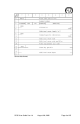
7. TROUBLE SHOOTING GUIDE The following is a list of possible error indicators or messages, what they indicate, and possible solutions to the source problem. If no solution is found, contact the factory for further assistance. 7.1 Error Blink Codes If the red LED issues a repeating blink code (accompanied by the drive not responding to SCSI commands), this indicates a hard error condition as listed in the table below. Contact the Memtech factory for repair service.
8. Appendix 8.1 Contact Information For Technical Support or Warranty Repair information, please contact Memtech at: 7628 Las Positas Road Livermore, CA 94550 U.S.A. Phone: (925) 294-8483 Fax: (925) 294-5920 Email: Info@memtech.com 8.2 SCSI specification information Information regarding the SCSI-II specification may be obtained from the following locations: Global Engineering 15 Inverness Way East Englewood, Co. 80112-5704 Phone: (303) 792-2181 or (800) 854-7179 Fax: (303) 792-2192 8.