MENDOTA GAS DIRECT VENT FIREPLACE WITH HEARTHGLO SEALED COMBUSTION SYSTEM Model DXV-42 STANDARD FRONT BAY FRONT INSTALLATION & OPERATING INSTRUCTIONS NO. 0806 WARNING: : This product must be installed by a licensed plumber or gas fitter when installed in the commonwealth of Massachusetts. Improper installation, adjustment, alteration, service or maintenance can cause injury or property damage. Refer to this manual.
TABLE OF CONTENTS LOCATING THE FIREPLACE AND GENERAL INFORMATION SPECIFICATIONS & CLEARANCES INSTALLATION INSTRUCTIONS GAS SUPPLY REQUIREMENTS GAS PRESSURE REQUIREMENTS FLUE VENTING LOCATIONS AND RESTRICTIONS FLUE VENTING INSTRUCTIONS FLUE VENTING COMPONENTS FLUE VENTING REQUIREMENTS LP GAS & HIGH ALTITUDE MINIMUM RISE THROUGH-THE-WALL VENTING VENT COMPONENTS PARTS LIST ELEVATED THROUGH-THE-ROOF VENTING VERTICAL THROUGH-THE-ROOF VENTING GRILL INSTALLATION GLASS DOOR OPERATION TIMBERFIRE LOG INSTALLATION INS
CONGRATULATIONS! You are the owner of a world class, heat producing, gas, direct vent, sealed combustion fireplace. This elegant, highly efficient Fireplace will be a constant source of comfort and fascination. It will be the focal point of beauty and interest in your home. The Mendota Gas Fireplace is a true heating appliance incorporating the traditional aesthetics of fireplace fire viewing with the controllability and fuel efficiency of a home gas furnace.
Your Mendota Gas Fireplace has a state-of-the-art co-axial direct vent, sealed combustion system. This advanced, highly efficient system brings in outside air for combustion, has a separate exhaust vent and efficiently heats and recirculates room air. The Mendota system maintains high air quality, maximizes efficiency and assures proper operation. SAFETY AND STRUCTURAL CONCERNS: The DXV Fireplace must be installed and serviced by a Mendota approved service person.
MENDOTA DXV-42 GAS DIRECT VENT FIREPLACE SPECIFICATIONS & CLEARANCES 31-3/4 15-1/2 45 5-1/2 63-1/2 6" OR 7" 90°L 12" FIGURE 1: Specifications & Clearances CAUTION: For L.P. & High Altitude (above 4,000 ft. but below 7,500 feet) 45º elbows must be used in place of 90º elbows. (SEE PG. 13). This requires 20" minimum to center of opening for the horizontal pipe to exit the wall.
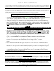
INSTALLATION INSTRUCTIONS CAUTION: Each installation must conform to all local, state and national codes. Refer to the national fuel gas code and local zoning and code authorities for details on installation requirements. The Mendota Fireplace must be vented to the outside in accordance with the latest edition of the National Fuel Gas Code. In the absence of local codes, the installation must conform to the most current edition of the National Fuel Gas Code ANSI Z223.1, also known as NFPA 54.
CORRECT GAS PRESSURE AND PROPER GAS SUPPLY LINE SIZING ARE IMPERATIVE TO THE SUCCESSFUL PERFORMANCE OF YOUR MENDOTA GAS FIREPLACE. BE SURE THE GAS SUPPLIER OR PLUMBER CAREFULLY CHECKS FOR CORRECT GAS PRESSURE AND GAS LINE SIZING WHEN INSTALLING THE FIREPLACE. IT IS CRITICAL TO CAREFULLY CHECK FOR GAS LEAKS WHEN HOOKING UP THE FIREPLACE -- CHECK WITH SOAP & WATER SOLUTION. BE SURE TO INSTALL "APPROVED" FLEX GAS LINE WITH BRASS-TO-BRASS FITTINGS TO PREVENT GAS LEAKS AT CONNECTIONS.
GAS PRESSURE REQUIREMENTS A MAJOR CAUSE OF OPERATING PROBLEMS WITH GAS APPLIANCES CAN BE IMPROPER GAS PRESSURE! Such problems as changes in flame color or configuration, gas pilot or burner outages, intermittent operation, changes in heat output, excessive burner noise, etc. are nearly always the result of changes in gas pressure or improper gas pressure at the time of the installation.
EXTERIOR VENT LOCATIONS AND RESTRICTIONS FIGURE 3: Exterior Vent Locations ∨ - Vent Terminal ∧ - Air Supply Inlet ≡ - Area where terminal is not permitted A= Clearance above grade, veranda, porch, deck, or balcony (*12 inches (30 cm) minimum) H= *Not to be installed above a meter/regulator assembly within three feet (90 cm) horizontally from the center-line of the regulator B= Clearance to window or door that may be opened (*12 inches (30 cm) minimum.
FLUE VENTING INSTRUCTIONS The Mendota Fireplace must be vented using the Mendota certified DuraVent or American Metals venting system.
FLUE VENTING COMPONENTS ITEM 1 1 1 1 2 3 4 *5 9 10 10 11 12 13 14 15 DESCRIPTION 12" VENT STACK 24" VENT STACK 36" VENT STACK 48" VENT STACK 90ºGALVANIZED ELBOW 45º GALVANIZED ELBOW ADJUSTABLE WALL THIMBLE 6” OR 7” PIPE ATTIC INSULATION SHIELD 12" ROOF FLASHING (0/12 TO 6/12) ROOF FLASHING (7/12 TO 12/12) STORM COLLAR VERTICAL VENT CAP SUPPORT BAND HORIZONTAL VENT CAP FIRESTOP SPACER Figure 5: Flue Venting Components For all DuraVent pipe sections and telescoping pipe sections, use Millpak 2000° SILICATE
FLUE VENTING REQUIREMENTS NOTE: FOR LP GAS & HIGH ALTITUDE, SEE PG. 13 MAX MAX 12 Figure 6: DXV42 Vertical & Horizontal Flex Vent Requirements when using Natural Gas NOTE: ONE 12” SECTION OF VERTICAL PIPE AND ONE 90O ELBOW CAN BE USED IF NO HORIZONTAL VENT SECTIONS GREATER THAN 7” ARE USED. ALL OTHER INSTALLATIONS MUST FALL WITHIN ABOVE SHADED AREA. NOTE: THE SHORTEST HORIZONTAL RUN OF 7”/6” ARE ACHIEVED USING EITHER THE 6” DURAVENT PIPE OR THE AMERIVENT 7” PIPE.
L.P. Gas or High Altitude (Above 4,000 Ft. but Below 7,500 Ft.) Minimum Height Required for Horizontal Termination NOTE 7” MAXIMUM SECTION CAN BE USED FOR HORIZONTAL RUNS. WARNING: For L.P. gas and high altitude installations (above 4,000 ft. but below 7,500 ft), 45° elbows must be used in place of 90° elbows. NOTE: This requires 32” minimum height to center. CAUTION: If 90° elbows must be used, a 3-foot vertical starter section must be used off the top of the fireplace.
A-1 MINIMUM RISE THROUGH-THE-WALL VENTING The minimum vertical rise required for through-the-wall horizontal vent terminations, for units using Natural Gas, and installed below 4,000 feet, is 17" from the top of the fireplace to the centerline of the 90º elbow. The 17” height is achieved using one 12” pipe section, vertically, and a 90 degree elbow. The maximum horizontal length pipe allowed using this configuration is 6” (Duravent) or 7” (Amerivent).
VENT COMPONENTS LIST MENDOTA # 45-01-00186 45-01-00187 45-01-00188 45-01-00189 45-01-00190 45-01-00191 45-01-00192 45-01-00193 45-01-00194 45-01-00195 45-01-00196 45-01-00197 45-01-00198 45-01-00199 45-01-00200 45-01-00201 45-01-00202 45-01-00203 45-01-00204 45-01-00206 45-01-00207 45-01-00208 45-01-00209 45-01-00210 45-01-00211 45-01-00212 45-01-00213 45-01-00214 45-01-00215 45-01-00216 45-01-00217 45-01-00218 45-01-00219 45-01-00220 AMERIVENT # 4D7 4D12 4D2 4D3 4D4 4D12A 4D45L 4D90L 4DW T 4DVC 4DHC 4D14S
A-2 ELEVATED RISE THROUGH-THE-WALL VENTING A maximum horizontal run of 12 ft. is allowed if a minimum vertical rise of 48” is used. Consult Figure 6, pg. 12 for maximum horizontal runs allowed when using vertical rises less than 48”. NOTE: The horizontal run of vent pipe must be level or have a ¼" rise for every 1' of run toward the termination. Never allow the vent to run downward. This will cause high temperatures and the possibility of a fire.
B-1 VERTICAL THROUGH-THE-ROOF VENTING The maximum straight vertical run of vent pipe is 36 ft. from the top of the fireplace. The fireplace will support a maximum run of 36 ft. Maintain 1" air space clearances on all sides of vertical vent-pipe sections and 2" clearances above any horizontal vent-pipe sections. IMPORTANT: REFER TO DRAWINGS ON PAGE 12& 13 WHILE FOLLOWING THESE INSTRUCTIONS. The DXV-42 Fireplace must be installed by a qualified Mendota approved serviceperson. 1.
8. Height "*H" of top of vent cap can be determined as follows: ROOF PITCH FLAT to 6/12 7/12 to 9/12 10/12 to 12/12 13/12 to 16/12 17/12 to 21/12 ROOF TERMINATION ASSEMBLY "H" DIMENSION FEET METERS 2 .6 2 .6 4 1.2 6 1.8 8 2.4 9. Complete installation with storm collar and vent cap.
DXV DOOR OPERATION TO REMOVE DOOR (FLAT SHOWN) 1. Place both thumbs on lower doorframe directly above Spring Loaded Door Holding Bar. 2. Reach fingers under Bar and pull Bar straight out from Fireplace front. 3. Pull Bar down and move Bar inward until Bar clears doorframe - then release. 4. Repeat procedure for opposite Holding Bar. 5. Carefully lift door straight up until doorframe "clears" the 3 Door Holding Tabs on top of firebox. 6.
TIMBERFIRE LOG SET INSTALLATION With door removed, proceed as follows: 1. Before placing log assembly in firebox, fill space under Log Grate with coals. 2. Follow the diagrams below in the sequence given. Start by identifying the Log Pins and Pin Hole in the Airbox. Next, identify the log pieces according to the diagram below. 3. Place glowing embers (wool) sparsely on top coals, in front of front log. Additional wool may be rubbed on front surfaces of log for additional glow.
2 0
2 1
2 2
2 3
The following Check Off Lists must be completed prior to final operation of the Fireplace, or manufacturer's warranty and liabilities will be voided: INSTALLATION CHECK OFF LIST Co-axial vent rigid pipe, wall vent cap or roof vent cap must be installed by a Mendota approved person in accordance with instructions. All joints must be secured, "twist-locked" and leak-proof. 2000º sealant must be used on the inner pipe joints of all DuraVent pipe sections.
LIGHTING INSTRUCTIONS IMPORTANT: Be sure all items on "INSTALLATION CHECK OFF LIST" (pg. 25) have been completed! CAUTION: If the pilot goes out, be sure to wait a minimum of five minutes before relighting - be sure to always remove the glass before relighting the pilot. 1. Remove glass door (see pg. 19) - ALWAYS LIGHT PILOT WITH GLASS REMOVED! 2. Make sure any gas supply shut-off cocks are open and Thermostat is "OFF". 3. Push in Gas Cock Dial Slightly and turn clockwise to "OFF".
THERMOSTAT OR REMOTE CONTROL OPERATION The Fireplace comes with a wall thermostat. The thermostat should be placed in the same room as the fireplace, approx. 4-5 ft. off the floor (out of reach of children). Do Not place thermostat near the fireplace or on an outside wall. CAUTION: BURNER SHOULD LIGHT IMMEDIATELY AFTER TURNING THERMOSTAT "ON". IF BURNER DOES NOT COME ON IMMEDIATELY TURN THE THERMOSTAT OFF AND WAIT 60 SECONDS BEFORE TURNING ON AGAIN.
MENDOTA BLOWER & BURNER REMOVAL & INSTALLATION BLOWER WIRING BURNER WELDMENT THERMO DISK BLOWER ASSEMBLY REMOVABLE BURNER PAN MAIN BURNER ORIFICE VALVE ASSEMBLY BLOWER WIRING DIAGRAM WARNING: Label all wires prior to disconnection when servicing controls. Wiring errors can cause improper and dangerous operation. Verify proper operation after servicing. BLOWER OPERATION The Mendota DXV Fireplace is designed so the blower operates at all times the fireplace is operating.
TROUBLE SHOOTING MENDOTA GAS DXV FIREPLACE SYMPTOM PROBABLE CAUSES CORRECTIVE ACTION 1. Thin black coating (soot) forms on viewing glass. A. Incorrect gas pressure Have gas supplier check for correct gas pressure (7" W.C. Nat. Gas; 11" W.C. LP Gas). If sooting continues open air shutter on burner (see "Gas Flame Adjustment" below). If sooting still continues, shut off unit and call Mendota service person. NOTE: To clean glass - remove glass and wipe glass with cloth or paper towel. B.
CUSTOMER INFORMATION AND TROUBLE-SHOOTING MAXIMUM ALLOWABLE SURFACE TEMPERATURE Mendota Fireplaces comply with UL Standards for maximum surface temperatures on exposed combustible surfaces adjacent to the unit. The Maximum allowable surface temperature is 117° F. over ambient (room) temperature. Thus, if a room is 70° – 80° the exposed combustible surfaces immediately surrounding the Fireplace can have a surface temperature as high as 187° F. – 197° F. (too hot to touch).
MAINTENANCE 1. ANNUAL MAINTENANCE OF MENDOTA UNITS IS REQUIRED. The following procedures must be performed each year by a Mendota approved service person. NOTE: Any adjustments to burner, pilot or logs must be done by a qualified Mendota service person. A. Clean all lint and dust built-up around the control. Inspect the condition of any wiring under the burner for melting or damage. B. Remove logs & coals and clean away any foreign matter (lint, carbon, etc.) on the burner and logs.
3. THE VIEWING GLASS SHOULD BE CLEANED PERIODICALLY. Exterior glass may be cleaned with cleaner as desired. Interior glass - use KEL KEM "Polish Plus" (#65-06-00455) or comparable product. Do Not use oven cleaner or abrasive cleaners to clean glass. DO NOT CLEAN WHEN GLASS IS HOT. 4. PERIODIC VISUAL CHECK OF BURNER AND PILOT FLAMES IS REQUIRED.
NATURAL TO LP GAS CONVERSION HA-20-00141 This conversion must be made by a qualified service technician. 1. Install main burner orifice #HA-11-00416 (#49 drill) see pg. 28 for location. Orifice is removed and installed with a ½” deep well socket and ratchet. 2. Install pilot orifice #05-04-00036 (.014”) see pg. 31 for location. Remove and install pilot hood with 7/16” open end wrench. (pilot orifice thimble is located inside pilot hood base) 3. Change L.P. screw (plug) #05-02-00294 as shown below.
REPLACEMENT PARTS MENDOTA GAS DXV-42 FIREPLACE PART NO HA-19-000121 DESCRIPTION DOOR GASKET 65-06-00336 HA-20-00120 GLASS - FLAT DOOR FRAME ASS'Y. – FLAT 65-06-00434 HA-20-00129 GLASS -BAY DOOR FRAME ASS'Y. – BAY 35-01-00268 35-01-00240 35-01-00239 35-01-00201 6 PIECE TIMBERFIRE LOG SET COALS 12 OZ BAY FOR 1 PC LOG SET GLOWING INSWOOL FIREBRICK KIT HA-20-00152 VALVE ASSEMBLY WITH LP CONVERSION VALVE NAT. GAS LP PLUG FOR NAT.
MENDOTA DESIGNER FRONTS INSTALLATION INFORMATION The following Designer Fronts are available for the DXV-42 Fireplace: 1. 2. 3. 4. 5. 6. Andover Arched Door Kit or Prairie Rectangular Door kit with Firescreen with optional Overlays as listed below: a. Black Overlay b. Pewter Overlay c. Antique Copper Overlay d.
Deerfield Front Specific Information The Deerfield is a full face front. DO NOT COVER THE FACEPLATE OF THE FIREPLACE WITH ANY MATERIALS. Furthermore, any drywall or wall covering material that is adjacent to the sides, top or bottom of the Fireplace’s faceplate may not protrude out past the front surface of the Fireplace Faceplate. The Minimum Required dimensions shown in the diagram below must be left bare and uncovered.
Information specific to the installation of Millenia Flat Grills, Victoria Filigrees and Tuscany Filigrees The Millenia Flat Grills, Victoria Filigree and Tuscany Filigree are designed to be “inside-fit” trim kits. All of these trim kits fit within the inner perimeter of the Fireplace’s Faceplate and remain flush within the Faceplate’s front surface, see Figure below.
"LABEL REPRESENTATION" DXV42 Also for use in mobile (manufactured) homes after first sale of home. Tested to ANSI Z21.88 (2002) – CSA 2.33 (2002) _________________________________________________ WARNING: Improper installation, adjustment, alteration, service or maintenance can cause property damage, personal injury, or loss of life. Refer to the owner's information manual provided with this appliance. Installation and service must be performed by a qualified installer, service agency or the gas supplier.
MENDOTA WARRANTY QUALIFICATION & SERVICE REFERENCE FORM As a part of Mendota's on-going program of customer satisfaction, this Form verifies proper installation and operation. It is important as a reference for future service. It insures long life and trouble-free operation of Mendota fireplaces & stoves and qualifies the owner for Mendota's lifetime limited warranty. Owner should sign Form when completed and mail a copy along with Warranty Registration to Mendota.
TAPE SHUT --------------------------------------------------------------------------------------------------------------------------------------------------------- POSTAGE NEEDED JOHNSON GAS APPLIANCE COMPANY 520 E AVENUE N.W.
NOTES 4 0
NOTES MENDOTA EXTENDED LIFETIME PROTECTION AND LIMITED WARRANTY 4 1
MENDOTA GAS FIREPLACE MODEL: _____ NAT. & L.P. Mendota Division of Johnson Gas Appliance Company, 520 E Avenue N.W. Cedar Rapids, Iowa 52405, extends this Extended Lifetime Protection and Limited Warranty to the original purchaser of a Mendota Gas Fireplace, Serial Number , which is limited and used under normal home conditions. STANDARD WARRANTY: JOHNSON GAS APPLIANCE CO.
Johnson Gas Appliance Company 520 E Avenue N.W. - Cedar Rapids, IA 52405 Mendota Hearth Division WEBSITE: WWW.JOHNSONGAS.COM or WWW.MENDOTAHEARTH.