
Operating instructions


EXTERIOR VENT LOCATIONS AND RESTRICTIONS
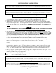
FIGURE 3: Exterior Vent Locations
∨ - Vent Terminal ∧ - Air Supply Inlet ≡ - Area where terminal is not permitted
A = Clearance above grade, veranda, porch, deck, or bal-
cony (*12 inches (30 cm) minimum)
H = *Not to be installed above a meter/regulator assembly
within three feet (90 cm) horizontally from the center-line
of the regulator
B = Clearance to window or door that may be opened
(*12 inches (30 cm) minimum.
I = Clearance to service regulator vent outlet (*6 feet (1.8m)
minimum)
C = Clearance to permanently closed window (minimum 12
inches (30 cm) recommended to prevent condensation
on window)
J = Clearance to non-mechanical air supply inlet to building or
the combustion air inlet to any other appliance.
(*12 inches (30 cm) minimum.
D = Vertical clearance to ventilated soffits located above the
terminal within a horizontal distance of two feet (60
cm) from the center-line of the terminal (18 inches (46
cm) minimum). Vinyl surfaces require 24 inches (60
cm).
K = Clearance to a mechanical air supply inlet (*6 feet (1.8 m)
minimum)
E = Clearance to unventilated soffits (12 inches (30 cm)
minimum). Vinyl surfaces require 24 inches (60 cm).
L = † Clearance above paved side-walk or a paved driveway
located on public property (*7 feet (2.1 m) minimum)
F = Clearance to outside corner - six inches (15 cm) M = Clearance under veranda, porch, deck, or balcony (24
inches (61 cm) minimum ‡)
G = Clearance to inside corner - 12 inches (30 cm). Vinyl
surfaces require 24 inches (60 cm).
† A vent shall not terminate directly above a sidewalk or paved driveway, which is located between two single-family
dwellings and serves both dwellings.
‡ Only permitted if veranda, porch, deck, or balcony, is fully open on a minimum of two sides beneath the floor.
* As specified in CGA B1: 19 Installation Codes (1991). Note: Local codes or regulations may require different clear-
ances.
8