FULLVIEW LINEAR DIRECT VENT GAS FIREPLACE HEATER Model ML47-PF2 INSTALLATION and OPERATING INSTRUCTIONS MANUAL DOCUMENT NO. ML47-PF2-IM-0814 WARNING: If the information in this manual is not followed exactly, a fire or explosion may result causing property damage, personal injury or loss of life. Do not store or use gasoline or other flammable vapors and liquids in the vicinity of this or any other appliance. WHAT TO DO IF YOU SMELL GAS Open windows. Do not touch electrical switches.
SAFETY AND WARNING INFORMATION FOR YOUR SAFETY WARNING: Improper installation, adjustment, altera- A qualified installer, service agency, or the gas supplier must perform installation and service. Do not store or use gasoline or other flammable vapors and liquids in the vicinity of this or any other appliance. WARNING Do not operate this appliance with the glass removed, cracked or broken. A licensed or qualified person should do replacement of glass. AVERTISSEMENT.
Due to high temperature, the appliance should be LOCATED out of traffic areas and away from furniture and draperies. En raison des températures élevées, l’appareil devrait être installé dans un endroit où il y a peu de circulation et loin du mobilier et des tentures. Clothing or flammable material SHOULD NOT BE PLACED on or near the appliance. On ne devrait pas placer de vêtements ni d’autres matières inflammables sur l’appareil ni à proximité.
Table of Contents SAFETY AND WARNING INFORMATION ........................................................................................................ 2 SPECIFIC REQUIREMENTS FOR THE COMMON WEALTH OF MASSACHUSETTS..................................... 6 ML47 FULL VIEW GAS FIREPLACE DIMENSIONS ......................................................................................... 7 ML47 FEATURES - QUICK REFERENCE INFORMATION ...............................................................................
EXTERIOR VENT LOCATIONS AND RESTRICTIONS................................................................................... 31 FLUE VENTING COMPONENTS IDENTIFICATION ....................................................................................... 32 ML47 MASTER FLUE VENTING REQUIREMENTS CHART .......................................................................... 33 IMPORTANT VENTING CONFIGURATION NOTES .......................................................................................
Specific Requirements for the Common Wealth of Massachusetts The information in this section applies to all installations performed in the Common Wealth of Massachusetts only.
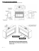
ML47 FULL VIEW GAS FIREPLACE DIMENSIONS OVERALL APPLIANCE DIMENSIONS AND FEATURES Lower Cover Plate Upper Cover Plate Removable Cover Plate for Plumbing & Electrical Access before unit is placed inside framed cavity. Replace Lower Cover Plate before sliding unit into framed cavity.
ML47 FEATURES - QUICK REFERENCE INFORMATION CERTIFICATION and LISTING: Certified under ANSI Z21.88 (2014) CSA 2.23 (2014) “Vented Gas Fireplace Heater " not for use with solid fuel. Not to be used as primary heat source. EFFICIENCY RATINGS: P.4 Fireplace Efficiency 71.3%. AFUE Natural Gas 70%, AFUE LP Gas 70.7% EXTERNAL DIMENSIONS: 54-1/4” Wide X 39” High X 19-1/2” Deep GLASS SIZE: NeoCeram Glass with non-reflective coating. Visible Glass measures 45” X 14-1/2”. Visible Glass Area 2 equals 652.5 in .
TECHNICAL SPECIFICATIONS FOR ML47 LINEAR ZC DECORATIVE FIREPLACE MODEL ML47 High Fire - Adjustable to Low Fire BTUH. (MODEL ML47) NAT. GAS 41,000 25,000 BTUH. (MODEL ML47) LP GAS 41,000 24,000 NOTE: LPG CONVERSION KIT, #HA-90-00110 MUST BE PURCHASED SEPARATELY TO CONVERT TO BURN LPG IN THIS FIREPLACE. MAIN ORIFICE [0-2000ft (610 m)]: 1/8” NG –: #49 LP [2000-4500ft (610-1370 m)]: #31 NG - #50 L.P. OVERALL EFFICIENCY: [P.4: 71.
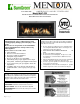
CONGRATULATIONS You are the owner of a world-class modern gas direct vent sealed combustion fireplace. This elegant, highly efficient Fireplace will be a constant source of comfort and fascination. It will be the focal point of beauty and interest in your home. This Mendota Gas Fireplace is an appliance incorporating modern aesthetics of fire viewing. Of particular interest is the low fuel consumption and brilliant fire viewing afforded by the latest technology combustion system.
ML47-M DIRECT VENT GAS FIREPLACE GENERAL APPLIANCE SPECIFICATIONS HIGH ALTITUDE INSTALLATION INFORMATION: Prior to installing at altitudes higher than 7500, please contact the Mendota technical service department for specific venting requirements and venting restrictions. 12 0 D IS T A N C E F R O M F IR E P L A C E F A C E A P P R O V E D M A N T E L P R O F IL E 11 | P a g e T H IS A R E A . A R E A .
MANTEL CLEARANCES Mantel Clearances for this fireplace may be measured from the top of the convection air opening or the floor level of this fireplace. The location that is referenced normally to measure mantel clearances is the Top of the Convection Air Opening. For ease, however, measure up from the floor level of this fireplace.
CLEARANCES TO COMBUSTIBLES FROM APPLIANCE SURFACES Figure 2: Clearances to Combustibles 0" C LEA RA N C E FRO M TO P STA N D O FFS 1 /2 " C LEA R A N C E FRO M BA C K CLEARANCE TO SIDE WALL PROJECTIONS Any side wall adjacent to Left or Right side of this appliance protruding of the front surface of the visible glass door and if perpendicular to the front surmust be located a minimum of 16" from the side edge of door.
PLANNING THE INSTALLATION When planning on appliance installation, it is necessary to determine the following information before installing: Where the appliance is to be installed. The vent system configuration to be used. Gas supply piping. Electrical Wiring. Framing and finishing details. Hearth Protection Pad Requirements. Whether accessories such as a wall switch, remote control, and ceiling fan are desired.
ROUGH FRAMING DIMENSIONS Rough Framing Dimensions The Rough Framing Dimensions must be mainMinimum Rough Framing Dimensions tained to allow this fireplace to slide into the fram0 DESCRIPTION DIMENSION (INCHES) ing cavity with a 90 elbow installed on the top A Width 54-1/4 starter collar.
FRAMING DEPTH and FINISHING GUIDES The general framing depth for this fireplace is 19-1/2 inches. See details about using the Adjustable Framing Bracket, below for flexibility for framing depths. For installing solid Granite or Marble slabs as fascia material, reduce the framing depth by ½” then install ½” thick drywall on the framing studs so that the drywall is flush with the front face of this fireplace. Install the Granite or Marble slab so that it adheres to the face of the fireplace and the drywall.
Adjustable Framing Brackets The ML-47 model is factory equipped with Top, Sides and Bottom adjustable framing brackets. These parts can slide backwards the thickness of the Finishing Material base substrate such as Durock, Hardibacker (in non-combustible zones) or Drywall board (in combustible material allowed zones). The framing depth shall be reduced by the thickness of the Finishing Material base.
Decorative Fronts Information: Traditions Front Only: The Traditions Front is approximately the overall size of the viewing glass frame. This Front mounts using steel barrel nuts on the outer sides of the viewing glass frame. The bracket attached to the Traditions Frame allows you to pull the Traditions outward in incremental steps up to 1”, maximum. The Traditions Front can be close to the glass frame or away from the glass frame.
Grace Front Only: The Grace Front’s inner edges start outside the convection air gaps around the viewing glass frame. This Front is mounted using steel spacers and screws on the outer sides of the convection air gap on the sides of the viewing glass frame. The bracket attached to the Grace Frame allows you to pull the Grace outward in incremental steps up to 2”, maximum.
Final Finishing Material mounted behind the Grace Front, using the Inner Guides: If the Final Finishing Material is mounted behind the Grace Front and you wish the front visible faces of the Grace Front and the Traditions or Willowbrook to be close to each other, you have one option: 1. Remove the Glass Safety Screen that is integrated on the back surface of the Grace Front. Install a Glass Safety Screen on the back surface of the Traditions or Willowbrook Front.
RAISED HEIGHT INSTALLATION OF ML47 The ML47 Linear Gas Fireplace may be installed in an elevated configuration. Please consult the table, below to determine the maximum raised height allowable based on the internal ceiling height of the room this Fireplace is installed in.
INSTALLATION OF FLAT PANEL TV ON TOP OF ML47 o All flat panel TVs are solid state electronic appliances and are vulnerable to ambient temperatures greater than 90 F. The ML47 is a gas fired heater and high ambient temperatures are to be expected in the immediate vicinity of this fireplace. If the installation of a Flat Panel TV is desired above this appliance, proceed with caution. Follow the specific framing dimension and instructions provided below.
ENAMEL PANORAMIC LINER AND FLOOR PLATE INSTALLATION REQUIREMENT There exist 5 color options for the required Panoramic Panel Kit. The Panoramic Panel and a matching floor plate are available in Black, Midnight Black, Copper, Mocha Metallic and Silver Metallic attractive colors. You must select one colored Panoramic Panel Kit and install it before any test firing of this appliance.
BACKUP DC POWER INLET PORT INSTALLATION Under normal conditions when AC power is available, this appliance is designed to operate on 110 VAC power. During power outages, it is designed to operate using 6 V DC backup power. This appliance is supplied with a DC power inlet harness, a single gang outlet box and two single cover plates. In addition, a 4 X AA size battery pack and a connector harness is also supplied.
GENERAL INFORMATION Your Mendota Gas Fireplace has a state-of-the-art co-axial direct vent, sealed combustion system. This advanced combustion system brings in outside air for combustion and directly exhausts through an exhaust vent. The Mendota system maintains high air quality and assures proper operation in today's "air-tight" homes.
GAS SUPPLY REQUIREMENTS Correct gas pressure and proper gas supply line sizing is imperative to the successful performance of your Mendota gas fireplace. Be sure the gas supplier or plumber carefully checks for correct gas pressure and gas line sizing when installing the fireplace. It is critical to check for gas leaks when connecting gas line to the fireplace -- check with soap & water solution.
regulator is of adequate capacity to service the gas appliances (such as dryer, furnace, etc.). If this regulator's capacity is not sufficient to add the Gas Fireplace, an additional "inches to inches" regulator must be installed for the Fireplace. EXCEPTION: Some codes allow 2-PSI (1.4KPA) supplies to enter the residence, in which case "pounds to inches" regulators are used. The following table provides information on correct gas pressure requirements.
GAS INPUT RATE VERICATION REQUIREMENTS Natural Gas Applications Gas Input Rate Verification Procedures Verify Main Orifice Size. The main orifice body has the orifice hole size stamped on it. NG orifice size shall be 1/8" for 0-2000 feet elevation and #31 for elevations exceeding 2000 feet. Verify that the Manifold Gas Pressure is within 3.5" WC +/- 1/8". Once setup, read the main home gas supply meter reading.
GENERAL INSTALLATION INSTRUCTIONS CAUTION: Each installation must conform to all local, state and national codes. Refer to the national fuel gas code and local zoning and code authorities for details on installation requirements. The Mendota Fireplace must be vented to the outside in accordance with the latest edition of the National Fuel Gas Code. In the absence of local codes, the installation must conform to the most current edition of the National Fuel Gas Code ANSI Z223.1, also known as NFPA 54.
GENERAL FLUE VENTING INSTRUCTIONS The Mendota Fireplace must be vented using the Mendota approved vent system components. Approved brands of vent components include DuraVent, Amerivent, Selkirk and Security vent pipes and venting components.
EXTERIOR VENT LOCATIONS AND RESTRICTIONS Figure 9: Exterior Vent ALL MEASUREMENTS FROM CENTER-LINE OF VENT CAP - Vent Terminal A= B= C= D= E= F= G= - Air Supply Inlet Clearance above grade, veranda, porch, deck, or balcony (*12 inches (30 cm) minimum). Vinyl surfaces require 24” min. Clearance to window or door that may be opened (*12 inches (30 cm) minimum.
FLUE VENTING COMPONENTS IDENTIFICATION DO NOT SEPARATE TELESCOPING SECTIONS. USE TELESCOPING SECTIONS AS COMPLETE ASSEMBLIES. HIGH ALTITUDE INSTALLATION INFORMATION: Prior to installing at altitudes higher than 7500, please contact the Mendota technical service department for specific venting requirements and venting restrictions.
ML47 MASTER FLUE VENTING REQUIREMENTS CHART NOTE: THIS CHART IS APPLICABLE TO NATURAL GAS ONLY. FOR LPG INSTALLATIONS, SEE TABLE ON LEFT SIDE OF THE CHART, BELOW. IMPORTANT NOTES: See Figure 15, below. Always use the longest vertical starter pipe section as the first vertical section attached to the fireplace directly. 18” minimum vertical section is required for Natural Gas and 24” minimum vertical section for LPG applications.
IMPORTANT VENTING CONFIGURATION NOTES See Figure 11 [MASTER FLUE VENTING REQUIREMENTS CHART AND TABLE FOR LPG APPLICATIONS]. HIGH ALTITUDE INSTALLATION INFORMATION: Prior to installing at altitudes higher than 7500, please contact the Mendota technical service department for specific venting requirements and venting restrictions.
APPROVED VENT SYSTEMS Figure 12: Vent Systems QUICK REFERENCE CHART S T R A IG H T U P , V E R T I C A L V E N T IN G Z E R O V E R T IC A L H O R IZ O N T A L T E R M IN A T IO N H H V E R T IC A L R IS E H O R IZ O N T A L T E R M IN A T IO N 40 FEET M A X IM U M V NO T ALLOW ED APPROVED APPROVED V E R T IC A L R IS E D U A L 90° ELBO W S H O R IZ O N T A L T E R M IN A T IO N H H1 V2 H2 V H V E R T IC A L R IS E D U A L 90° ELBO W S V1 Z E R O V E R T IC A L V E R T IC A L T E R M IN
ZERO RISE HORIZONTAL TERMINATION The ML47 Fireplace must be installed by a qualified Mendota approved serviceperson. When the minimum 18” vertical and following 90-degree elbow is connected directly to this fireplace, the horizontal centerline of the 90ºelbow will be 53” inches up from the floor level of this Fireplace. See Figure 11, MASTER FLUE VENTING REQUIREMENTS CHART and Figure 14 and Figure 13 below. Figure 13 Use "fixed" pipe sections in place of adjustable pipe section s wherever possible.
VERTICAL RISE HORIZONTAL TERMINATION The minimum vertical section required to be connected directly to the starter adapter on this fireplace is 48 inches when used with a maximum horizontal run of 32 ft. If the total length of the vertical sections connected directly to the starter adapter on this fireplace is between 4 feet and 41 feet, you are allowed a maximum 32 feet horizontal run. For other venting configurations within these maximum limits, see Figure 15, Zone A and Zone B.
Figure 16 V min H1 +H2 max 24 in. 2 ft. 30 in. 9 ft. 36 in. 15 ft. 42 in. 21-1/2 ft. 48 in. 28 ft. 4 ft. - 10 ft. 28 ft. 10 ft. - 40 ft. Varies Figure 17 V1 min H1 +H2 max 24 in. 2 ft. 30 in. 9 ft. 36 in. 15 ft. 42 in. 21-1/2 ft. 48 in. 28 ft. 4 ft. - 10 ft. 28 ft. 10 ft. - 40 ft. Varies 38 | P a g e V2 MAX 10 ft. 10 ft. 10 ft. 10 ft. 10 ft.
VERTICAL THROUGH-THE ROOF VENTING The maximum vertical run of vent pipe is 40 ft. from the top of the fireplace. The fireplace will support a run of a maximum of 40 ft. Maintain 1" air space clearances on all sides of vents (3" above horizontal runs). o If an offset is required directly on top of the fireplace, two 45 elbows may be connected directly to the top of this fireplace to create a horizontal offset then to run upwards vertically.
. Figure 19 Figure 18 V1 min H max 18 in. 6 in. 24 in. 6 ft. 30 in. 13 ft. 36 in. 19 ft. 42 in. 25-1/2 ft. 48 in. 32 ft. 4 ft. - 10 ft. 32 ft. 10 ft. - 40 ft. Varies 40 | P a g e V2 max 38-1/2 ft. 34 ft. 27 ft. 21 ft. 14-1/2 ft. 10 ft.
0 VERTICAL THROUGH-THE-ROOF VENTING USING FOUR 90 ELBOWS 0 In extreme situations, Four 90 elbows may be required to reach a proper exit point for the vent system. Mendota has spent considerable time and effort in the design of this fireplace and its venting system. Through this effort, Mendota has 0 been able to certify the use of Four 90 elbows. 0 The use of Four 90 elbows must meet some minimum prerequisites. Prerequisite #1: The vent system must terminate vertically using a vertical vent cap.
ML47 DOOR OPERATION TO REMOVE DOOR Use the glass latch tool to disconnect the spring latches from the glass frame. Insert tool into hole in latch, pull towards you and Rotate 90 degrees to disengage top latches. Remove tool. There are two spring latches on top of this gas fireplace. With both hands, rotate top edge of glass frame away from unit 8 inches. Lift glass frame up 1 inch, at an angle, and move away from unit. Door is now free from unit.
The following Check-Off Lists must be completed prior to final operation of the Fireplace. INSTALLATION CHECK OFF LIST Co-axial vent rigid pipe, wall vent cap or roof vent cap must be installed by a Mendota approved person in accordance with instructions. All joints must be secured, "twistlocked" and leak-proof. 1000ºF sealant must be used on the inner pipe joints of all DuraVent pipe sections.
ML47 BURNER MEDIA INSTALLATION INSTRUCTIONS WARNING: Failure to position the parts in accordance with these diagrams or failure to use only parts specifically approved with this appliance may result in property damage or personal injury.” AVERTISSEMENT. Risque de dommages ou de blessures si les pièces ne sont pas installées conformément à ces schémas et ou si des pièces autres que celles spécifiquement approuvées avec cet appareil sont utilisées.
LOCATION OF MASTER SWITCH AND SYNC SWITCH The Master Switch and Sync Switch are located 9-3/4” to right from the left edge of the glass frame and under the bottom edge of the glass frame in the bottom air gap. Use the glass latch tool to actuate the two switches. The Master Switch must be ON for the pilot flame and burner flames to activate. The SYNC switch is to be used initially when mating the remote transmitter with the receiver located within this appliance body.
BEFORE YOU BEGIN Read this entire manual before you use your new fireplace (especially the section “Safety Precautions” on page 2). Failure to follow the instructions may result in property damage, bodily injury, or even death. Remote Control Transmitter Functions NOTE: The Wall Receiver will “beep” once every time a Remote Transmitter Key is pressed, signaling that the command has been received.
REMOTE TRANSMITTER OPERATING INSTRUCTIONS TO TURN ON THE APPLIANCE: Press the ON/OFF button. The transmitter display will show all active icons on the screen. Select the Thermostat Mode by pressing the Thermostat Key: OFF (meaning Manual Mode), ON (meaning normal Thermostat) or Smart (meaning Smart Mode). In OFF (Manual Mode), the appliance will ignite and start on HI. In ON (Normal Thermostat Mode), the appliance will only ignite if the Set Temperature is greater than the Room Temperature.
o o TEMPERATURE INDICATOR ( F or C) Press the ON/OFF Key and Turn Off the Fireplace. Simultaneously, Press both the MODE Key and the Thermostat Key. o Look at the LCD display to verify that your desired indicator ( F or o C) is being displayed. If not, repeat step 2. KEY LOCK FUNCTION To prevent unsupervised children from operating the fireplace, a KEY LOCK function is provided with this remote control system. To activate the KEY LOCK function, simultaneously press the “MODE KEY” and the “UP KEY”.
“FIRST TIME” PILOT LIGHTING INSTRUCTIONS IMPORTANT: Be sure all items on "INSTALLATION CHECK OFF LIST" in the Installation Manual have been completed! CAUTION: If the pilot goes out, be sure to wait a minimum of five minutes before attempting to relight the pilot. Make certain that any manual gas supply shut-off valves located upstream of fireplace are open and the Master On/Off switch is toggled to the ON position.
IPI/STANDING PILOT SYSTEM INFORMATION Supply voltage Ambient temperature ratings Radio Frequency REMOTE CONTROL 4.5V (three 1.5V AAA batteries) o o 32 – 122 F (0 – 50 C) 315 MHz WALL RECEIVER 6.0V (four 1.5V AA batteries) o o 32 – 140 F (0 – 60 C) 315 MHz ATTENTION! The transmitter and receiver are RADIO FREQUENCY DEVICES. Placing the receiver in or near metal may severely reduce the signal range.
TROUBLE SHOOTING THE ML47 FIREPLACE & MAINTENANCE INFORMATION SYMPTOM PROBABLE CAUSES CORRECTIVE ACTION 1. Thin black coating (soot) forms on viewing glass. A. Incorrect gas pressure or improper orifice size. Have gas supplier check for correct gas inlet pressure (7" W.C. Nat. Gas; 11" W.C. LP Gas). If sooting continues, open air shutter on burner (see "Gas Flame Adjustment" below). If sooting still continues, shut off unit and call Mendota service person.
MAINTENANCE ANNUAL MAINTENANCE OF MENDOTA UNITS IS REQUIRED. The following procedures must be performed each year by a Mendota approved ser1 " M IN . vice person. NOTE: Any adjustments to burner, pilot or burner media must be done by a qualified Mendota service person. Clean all lint and dust build-up around the control. Inspect the condition of any wiring under the burner for melting or damage. A. Remove media and clean away any foreign matter (lint, Carbon, etc.
BASIC MAINTENANCE To access internal components for general service or maintenance requirements, remove any decorative front, remove the glass door, remove all burner media, inner Panoramic Lining and floor plate, remove main burner. Locate two access plates on the left and right side of firebox floor. See diagrams, below. Unscrew seven outer screws and lift entire left or right cover plate assembly which provides access to inner electronic components and gas train systems.
NATURAL TO LP GAS CONVERSION Kit # HA-90-00110 for Mendota Model ML47 This conversion kit shall be installed by a qualified service agency in accordance with the manufacturer’s instructions and all applicable codes and requirements of the authority having jurisdiction. If the information in these instructions is not followed exactly, a fire, explosion or production of carbon monoxide may result causing property damage, personal injury or loss of life.
WARNING: It is of the utmost importance that the correct burner orifice be installed Turn off gas supply at the appliance service valve. See written instructions that accompany the LP pressure regulator. 1. Using a Torx T20 or a slotted screwdriver, remove 2 screws that secure the NG Pressure Regulator to the gas valve body and remove NG Pressure Regulator, see following page. 2.
LP PRESSURE REGULATOR CONVERSION INSTRUCTIONS WARNING: Failure to position the parts in accordance with these diagrams or failure to use only parts specifically approved with this appliance may result in property damage or personal injury.” AVERTISSEMENT. Risque de dommages ou de blessures si les pièces ne sont pas installées conformément à ces schémas et ou si des pièces autres que celles spécifiquement approuvées avec cet appareil sont utilisées.
LP GAS PRESSURE REQUIREMENTS Inlet and manifold gas pressure checking taps are located on gas valve. These ports are only accessible from the outer left side of the fireplace. A qualified installer shall take pressure measurements at these ports to verify and set the correct gas pressures during the LP Kit installation and before fascia materials are installed over the front of this fireplace.
CHECKING FOR NORMAL BURNER (S) IGNITION CHARACTERISTICS Once the conversion to LPG and all the above steps have been completed, install Burner Media and light the main burner. On the Remote Transmitter, push On/Off button to ON . Change Thermostat Mode to "MANUAL". The pilot system will begin to spark and then the Main burner should light and flame should not "lift" off burner.
ML47 VALVE ASSEMBLY REPLACEMENT PARTS ML47 VALVE ASSEMBLY REPLACEMENT PARTS LIST PART ITEM QTY NUMBER DESCRIPTION 1 1 05-04-00062 Pilot Assembly 2 2 65-14-00180 ORIFICE, 1/8” 3 1 HA-90-00004 Proflame Valve Assembly with fittings 4 1 55-02-00070 TUBING, 3/8" OD X 12 SS 304 Figure 22: ML47 VALVE ASSEMBLY 59 | P a g e
ML47 GAS IGNITION SYSTEM WIRING DIAGRAM Optional Fan Kit The appliance must be electrically connected and grounded in accordance with local codes or, in the absence of local codes, with the current NFPA 70-National Electric Code or CSA C22.1-Canadian Electrical Code. Caution: Label all wires prior to disconnection when servicing controls. Wiring errors can cause improper and dangerous operation” and “Verify proper operation after servicing.
GLASS FRAME ASSEMBLY REPAIR AND REPLACEMENT GASKET DO NOT substitute other manufacturer's materials or components. DO NOT operate unit with cracked, broken or missing glass. DO NOT abuse the glass door by striking the glass, slamming the door shut, etc WARNING Use only authorized parts and materials obtained from Johnson Gas ApplianceGCompany L A S S when replacing defective or damaged glass. WARNING Do not operate this appliance with the glass removed, cracked or broken.
LISTING LABEL INFORMATION The model information regarding your specific appliance can be found on the rating plate, which is located in the air gap below the glass frame near the center. When contacting your dealer for any cleaning service or warranty service, always provide the Model Number, Serial Number and Manufactured Date. This information will expedite the warranty verification process.
THIS PAGE LEFT BLANK, INTENTIONALLY.
THIS PAGE LEFT BLANK, INTENTIONALLY.
MENDOTA WARRANTY QUALIFICATION & SERVICE REFERENCE FORM As a part of Mendota's on-going program of customer satisfaction, this Form verifies proper installation and operation. It is important as a reference for future service. It insures long life and trouble-free operation of Mendota fireplaces & stoves and qualifies the owner for Mendota's lifetime limited warranty. Owner should sign Form when completed and mail a copy along with Warranty Registration to Mendota.
TAPE SHUT POSTAGE NEEDED JOHNSON GAS APPLIANCE COMPANY 520 E AVENUE N.W.
MENDOTA EXTENDED PROTECTION AND LIMITED WARRANTY MENDOTA ML47 DIRECT VENT FIREPLACE Mendota Division of Johnson Gas Appliance Company, 520 E Avenue N.W. Cedar Rapids, Iowa 52405, extends this Extended Protection and Limited Warranty to the original purchaser of a Mendota FV46 Fireplace, which is limited and used under normal home conditions. STANDARD WARRANTY: JOHNSON GAS APPLIANCE CO.
Johnson Gas Appliance Company 520 E Avenue N.W. - Cedar Rapids, IA 52405 Mendota Hearth Division WEBPAGE: www.johnsongas.com or www.mendotahearth.