
Operating instructions
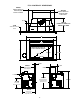
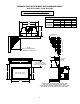
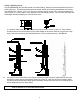
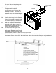

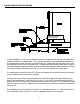

Table Of Contents
- SAFETY AND WARNING INFORMATION
- Specific Requirements for the Common Wealth of Massachusetts
- Building Permit and Installation Inspection Approval Requirements
- GENERAL INFORMATION
- FV33-M OVERALL DIMENSIONS
- SPECIFICATIONS & CLEARANCES
- INSTALLATION INSTRUCTIONS
- FLUE VENTING
- RAISED HEARTH SPECIFICATIONS
- GAS SUPPLY REQUIREMENTS
- If the factory-built fireplace has no gas access hole(s) provided, an access hole 1.5” or less may be drilled through the lower sides or bottom of the firebox in a proper workmanship like manner. This access hole must be plugged with non-combustible...
- GAS PRESSURE REQUIREMENTS
- WARNING: Do not operate appliances with glass front removed, cracked, or broken. Replacement of glass should be done a licensed or qualified service person.
- ELECTRICAL REQUIREMENTS
- HIGH ALTITUDE INSTALLATIONS
- INSTALLATION CHECK OFF LIST
- LIGHTING CHECK OFF LIST
- DOOR REMOVAL AND REPLACEMENT
- CAUTION: Do not operate the appliance with glass removed, cracked or broken. Replacement of the glass should be done by a licensed or qualified service person. Glass latch tool #HA-57-00743 is supplied with the unit.
- To Unlatch Glass Frame Latches:
- FV33-M BURNER MEDIA INSTALLATION INSTRUCTIONS
- FLAME APPEARANCE ADJUSTMENT
- REMOTE TRANSMITTER OPERATING INSTRUCTIONS
- TO TURN ON THE APPLIANCE:
- TO TURN OFF THE APPLIANCE, press the ON/OFF button.
- MODE KEY: Pressing the MODE KEY toggles between the various available functions: Flame Height, Fan Speed, Accent Light Dimmer and Secondary Burner On/Off.
- Flame Height: 6 flame height Levels are available. While the Flame Height Icon is displayed, pressing the Up or Down button once will increase or decrease the flame height by 1 of 6 increments. If the flame height is at Level 1 and the Down button is...
- Fan Speed Control: The fan speed can be adjusted through six (6) speeds and OFF. To activate this function, press the MODE Key to index to the fan control icon. Use the UP/Down Arrow Key to turn ON, OFF or adjust the fan speed. A single “beep” will...
- Accent-Light Dimmer: This function controls the Mendota Accent Light functions. Pressing the UP key in this mode will TURN ON the Accent Light and allow you to control the brightness of the Accent Light in 6 steps. A single “beep” will confirm recep...
- Secondary Burner: This function is NOT available. Skip past this icon.
- NOTE: The “AUX” function is not available and shall be skipped over. TEMPERATURE INDICATOR (oF or oC)
- KEY LOCK FUNCTION
- LOW BATTERY POWER DETECTION
- OPERATING DURING POWER OUTAGES
- You may operate this appliance indefinitely on battery power as long as you accept that high capacity DC 6 volt batteries will be required to sustain uninterrupted DC power to this appliance and that the blower function and accent light functions will...
- IPI/STANDING PILOT SYSTEM INFORMATION
- NOTE: SPLIT FLOW VALVE IS NOT USED IN THIS PRODUCT.
- MAINTENANCE
- NATURAL TO LP GAS CONVERSION INSTRUCTIONS
- LP PRESSURE REGULATOR CONVERSION INSTRUCTIONS
- LP GAS PRESSURE REQUIREMENTS
- CHECKING FOR NORMAL BURNER (S) IGNITION CHARACTERISTICS
- WARNING: Do not operate appliances with glass front removed, cracked, or broken. Replacement of glass should be done a licensed or qualified service person.
- BLOWER OPERATION AND WIRING
- BASIX SURROUNDS AND FACEPLATES INFORMATION
- Design(C) 1-3/4” outer edge return
- The 1-3/4” outer border return allows installation of this insert in fireplace cavities with depths greater than 15-3/8”.
- SPECIAL NOTE FOR 1-3/4” RETURN DESIGNS: The Basix and Faceplates with 1-3/4” returns may not have the Backup DC Power Inlet Port Knock Outs on the left face and left edge return. You will be required to leave the DC Power Inlet Port fitting in the fa...
- CUSTOMER INFORMATION AND TROUBLE-SHOOTING
- TROUBLE SHOOTING MENDOTA GAS FIREPLACE INSERT
- BURNER FLAMES ADJUSTMENT- AIR INTAKE DAMPER CONTROLS
- BURNERS AIR SHUTTER CONTROLS
- REPLACEMENT AND SERVICE PARTS
- GLASS FRAME ASSEMBLY REPAIR AND REPLACEMENT
- MENDOTA WARRANTY QUALIFICATION & SERVICE REFERENCE FORM
- MENDOTA EXTENDED LIFETIME PROTECTION AND LIMITED WARRANTY

12
INSTALLATION INSTRUCTIONS
CAUTION: Each installation must conform to all local, state and national codes. Refer to the national fuel gas code and local zoning and code authorities for details on
installation requirements. The Mendota Inserts must be vented to the outside in accordance with the latest edition of the National Fuel Gas Code. In the absence of local
codes, the installation must conform with National Fuel Gas Code ANSI Z223.1 (NFPA 54), or Canadian Code CAN1-B149 or most current edition, also known as
NFPA 54. Do not connect this Insert to a chimney flue serving a separate solid fuel or gas-burning appliance.
1. Remove glass doors, metal fire screens, etc. from existing fireplace. Be sure there is 12" minimum dis-
tance from top of upper grill to bottom of mantel; see Specifications (Pg.11 & 5), and a 16" minimum non-
combustible hearth extension in front of the glass surface if a raised hearth is not supplied. (See pg. 17
for "Raised Hearth").
2. Remove any additional framework or other obstructions in the existing fireplace opening and burning area.
Also remove any chimney cap from top of chimney so that vent liner can be installed freely.
3. Before Insert is installed, have gas supplier or contractor run gas line to the existing fireplace. Be sure gas
plumbing instructions [see Pg. 18 & 19 are carefully followed. Gas supply may enter fireplace on either
side or back of fireplace, whichever is most convenient and accessible. Electrical service (120 volt) should
also be supplied.
4. The entire chimney should be swept to remove creosote, soot and any obstructions (bird nests, etc.).
5. Open fireplace damper. If damper opening is large enough to accept the 4" and 3" flue liners, permanent-
ly secure damper in "open" position. NOTE:
Massachusetts requires that the flue damper must be re-
moved or permanently welded in the "open" position.
6. If damper opening is too small for the 4" & 3" flue liners, it will be necessary to remove the damper handle
and the damper plate. Some damper plates are held in place by a pinned hinge that can be released easily
by tapping out the pin with a hammer and punch. Others may be held in place by a screw or bolt, or piv-
ots may be cast into the damper housing. The pinned-hinged types may be harder to get out and may re-
quire sawing or breaking out. [NOTE: if flue size is 6" (127 mm) or less, or if severe offsets occur, or a
significant mortar slop is evident between the liners, try to snake liner down the chimney to the top of the
damper housing before breaking out damper plate and housing.]
CAUTION: If the 4" & 3" flue liners cannot be installed in an extremely tight chimney DO NOT proceed
with installation.
7. If damper opening is narrower than 4-1/2" to 5" (114 mm to 127 mm) and if local code authorities allow,
loosen and remove mortar behind back side of damper housing in the center of the opening enough to get
the gripping teeth of a pipe wrench over the flange of the damper housing (for cast iron housings). Tight-
en the wrench snugly, and kick down on the wrench handle to break out a half moon shaped piece of the
damper housing, enough to easily fit the flex liner through it. If the opening is wide enough, the break out
is not necessary.
8. Install Insert only in chimney heights of 10' (minimum) to 70' (maximum) -- as measured in
step 9 below.
9. Measure the chimney height from the top of the chimney (or the existing flue liner) to a point 24" (610
mm) above the floor of the fireplace hearth. It may be necessary to drop a rope and measure the rope it-
self. Be sure to allow for all offsets in existing chimney. Cut the 4" and 3”diameter flex liner (s) to this
measured length.