
Operating instructions
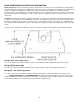
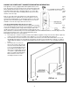
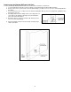
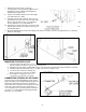
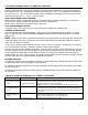
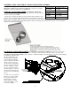
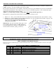
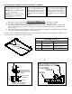
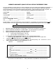
Table Of Contents
- SAFETY AND WARNING INFORMATION
- Specific Requirements for the Common Wealth of Massachusetts
- Building Permit and Installation Inspection Approval Requirements
- GENERAL INFORMATION
- FV33-M OVERALL DIMENSIONS
- SPECIFICATIONS & CLEARANCES
- INSTALLATION INSTRUCTIONS
- FLUE VENTING
- RAISED HEARTH SPECIFICATIONS
- GAS SUPPLY REQUIREMENTS
- If the factory-built fireplace has no gas access hole(s) provided, an access hole 1.5” or less may be drilled through the lower sides or bottom of the firebox in a proper workmanship like manner. This access hole must be plugged with non-combustible...
- GAS PRESSURE REQUIREMENTS
- WARNING: Do not operate appliances with glass front removed, cracked, or broken. Replacement of glass should be done a licensed or qualified service person.
- ELECTRICAL REQUIREMENTS
- HIGH ALTITUDE INSTALLATIONS
- INSTALLATION CHECK OFF LIST
- LIGHTING CHECK OFF LIST
- DOOR REMOVAL AND REPLACEMENT
- CAUTION: Do not operate the appliance with glass removed, cracked or broken. Replacement of the glass should be done by a licensed or qualified service person. Glass latch tool #HA-57-00743 is supplied with the unit.
- To Unlatch Glass Frame Latches:
- FV33-M BURNER MEDIA INSTALLATION INSTRUCTIONS
- FLAME APPEARANCE ADJUSTMENT
- REMOTE TRANSMITTER OPERATING INSTRUCTIONS
- TO TURN ON THE APPLIANCE:
- TO TURN OFF THE APPLIANCE, press the ON/OFF button.
- MODE KEY: Pressing the MODE KEY toggles between the various available functions: Flame Height, Fan Speed, Accent Light Dimmer and Secondary Burner On/Off.
- Flame Height: 6 flame height Levels are available. While the Flame Height Icon is displayed, pressing the Up or Down button once will increase or decrease the flame height by 1 of 6 increments. If the flame height is at Level 1 and the Down button is...
- Fan Speed Control: The fan speed can be adjusted through six (6) speeds and OFF. To activate this function, press the MODE Key to index to the fan control icon. Use the UP/Down Arrow Key to turn ON, OFF or adjust the fan speed. A single “beep” will...
- Accent-Light Dimmer: This function controls the Mendota Accent Light functions. Pressing the UP key in this mode will TURN ON the Accent Light and allow you to control the brightness of the Accent Light in 6 steps. A single “beep” will confirm recep...
- Secondary Burner: This function is NOT available. Skip past this icon.
- NOTE: The “AUX” function is not available and shall be skipped over. TEMPERATURE INDICATOR (oF or oC)
- KEY LOCK FUNCTION
- LOW BATTERY POWER DETECTION
- OPERATING DURING POWER OUTAGES
- You may operate this appliance indefinitely on battery power as long as you accept that high capacity DC 6 volt batteries will be required to sustain uninterrupted DC power to this appliance and that the blower function and accent light functions will...
- IPI/STANDING PILOT SYSTEM INFORMATION
- NOTE: SPLIT FLOW VALVE IS NOT USED IN THIS PRODUCT.
- MAINTENANCE
- NATURAL TO LP GAS CONVERSION INSTRUCTIONS
- LP PRESSURE REGULATOR CONVERSION INSTRUCTIONS
- LP GAS PRESSURE REQUIREMENTS
- CHECKING FOR NORMAL BURNER (S) IGNITION CHARACTERISTICS
- WARNING: Do not operate appliances with glass front removed, cracked, or broken. Replacement of glass should be done a licensed or qualified service person.
- BLOWER OPERATION AND WIRING
- BASIX SURROUNDS AND FACEPLATES INFORMATION
- Design(C) 1-3/4” outer edge return
- The 1-3/4” outer border return allows installation of this insert in fireplace cavities with depths greater than 15-3/8”.
- SPECIAL NOTE FOR 1-3/4” RETURN DESIGNS: The Basix and Faceplates with 1-3/4” returns may not have the Backup DC Power Inlet Port Knock Outs on the left face and left edge return. You will be required to leave the DC Power Inlet Port fitting in the fa...
- CUSTOMER INFORMATION AND TROUBLE-SHOOTING
- TROUBLE SHOOTING MENDOTA GAS FIREPLACE INSERT
- BURNER FLAMES ADJUSTMENT- AIR INTAKE DAMPER CONTROLS
- BURNERS AIR SHUTTER CONTROLS
- REPLACEMENT AND SERVICE PARTS
- GLASS FRAME ASSEMBLY REPAIR AND REPLACEMENT
- MENDOTA WARRANTY QUALIFICATION & SERVICE REFERENCE FORM
- MENDOTA EXTENDED LIFETIME PROTECTION AND LIMITED WARRANTY
42
How to move the Backup DC Power Inlet Port
To move the Backup Battery Power Inlet Port to a new location, follow these instructions.
1. Locate the DC Power Inlet Port connector which is mounted directly beneath the Master Switch.
2. A large cutout exist on the left side of the unit which will give you direct access to the rear of the Backup DC Inlet
Port fitting.
3. Loosen and remove the securing nut for the Inlet Port fitting then lift it up and out carefully while guiding the wires
through the open slot.
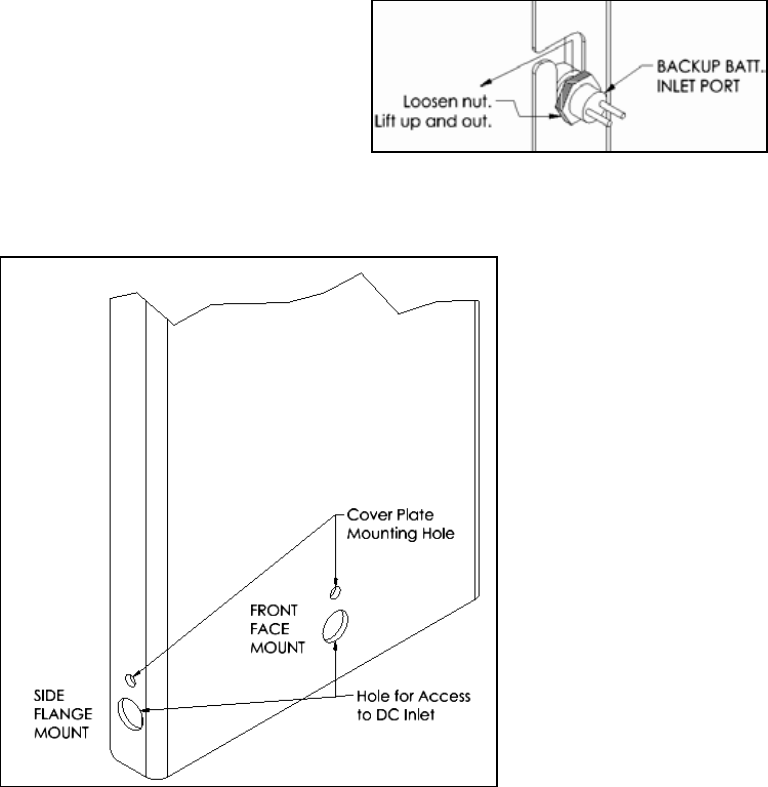
4. Carefully pull the Inlet Port fitting and its connecting cable out
of the body of this appliance through a hole provided at the
front of the Left Control Panel.
5. Determine where you wish to mount the DC Inlet Port (front
face or left side return flange).
6. Push the partially cutout knockouts through carefully using a
small screw driver.