FULLVIEW DIRECT VENT GAS FIREPLACE HEATER Model FV46 INSTALLATION INSTRUCTIONS MANUAL DOCUMENT NO. FV46-IM-0412 WARNING: If the information in this manual is not followed exactly, a fire or explosion may result causing property damage, personal injury or loss of life. Do not store or use gasoline or other flammable vapors and liquids in the vicinity of this or any other appliance. WHAT TO DO IF YOU SMELL GAS • Open windows. • Do not touch electrical switches. • Do not try to light any appliance.
SAFETY AND WARNING INFORMATION FOR YOUR SAFETY A qualified installer, service agency, or the gas supplier must perform installation and service. Do not store or use gasoline or other flammable vapors and liquids in the vicinity of this or any other appliance. WARNING Do not operate this appliance with the glass removed, cracked or broken. A licensed or qualified person should do replacement of glass. AVERTISSEMENT.
Always KEEP the appliance clear and free from combustible materials, gasoline, and other flammable vapors and liquids. NEVER OBSTRUCT the flow of combustion and ventilation air. Keep the front of the appliance CLEAR of all obstacles and materials for servicing and proper operation. Due to high temperature, the appliance should be LOCATED out of traffic areas and away from furniture and draperies.
TABLE OF CONTENTS SAFETY AND WARNING INFORMATION................................................................................................................................................. 2 FV46 FULL VIEW GAS FIREPLACE DIMENSIONS .................................................................................................................................. 6 TECHNICAL SPECIFICATIONS FOR FV46 .............................................................................................................
Specific Requirements for the Common Wealth of Massachusetts The information in this section applies to all installations performed in the Common Wealth of Massachusetts only. a) For all side wall horizontally vented gas fueled equipment installed in every dwelling, building or structure used in whole or in part for residential purposes and where the side wall exhaust vent termination is less than seven (7) feet above grade, the following requirements shall be satisfied: 1.
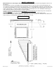
FV46 FULL VIEW GAS FIREPLACE DIMENSIONS OVERALL APPLIANCE DIMENSIONS AND FEATURES 36 5/8 WALL RECEIVER & LIGHT HARNESS 9 3/8 13 5"X8" COAXIAL VENT CONNECTOR WOOD FRAMING STANDOFF TOP 44 1" FINISHING GUIDE DEPTH 22 3/8 39 7/8 OUTER GUIDES 38 in. INNER GUIDES 35-3/4" OUTER GUIDE HEIGHT 41 1/2" FNPT GAS INLET 4 7/8" 47 7/8 13 7/8" 9 7/8" 3" 110 VAC INLET 39 5/8 1 9/16" MAX.
TECHNICAL SPECIFICATIONS FOR FV46 MODEL FV46 BTUH. (MODEL FV-46) BTUH. (MODEL FV-46) High Fire - Adjustable to - Low Fire NAT. GAS LP GAS 45,500 45,500 13,450 15,840 NOTE: LPG CONVERSION KIT, #HA-88-0080, MUST BE PURCHASED SEPARATELY TO CONVERT TO BURN LPG IN THIS FIREPLACE. MAIN ORIFICE [0-2000ft (610 m)]: REAR BURNER: #37 NAT. GAS [1/16” L.P. GAS] – FRONT BURNER: #44 NAT. [#55 LP] OVERALL EFFICIENCY: AFUE RATING = 72.8%, P.4 Heating Seasonal Efficiency = 76.9%,P.4 Fireplace Efficiency = 76.9% P.
CONGRATULATIONS You are the owner of a world-class heat producing gas direct vent sealed combustion fireplace. This elegant, highly efficient Fireplace will be a constant source of comfort and fascination. It will be the focal point of beauty and interest in your home. This Mendota Gas Fireplace is a true heating appliance incorporating modern aesthetics of fire viewing with the controllability and fuel efficiency of a home gas furnace.
FV46-M DIRECT VENT GAS FIREPLACE GENERAL APPLIANCE SPECIFICATIONS HIGH ALTITUDE INSTALLATION INFORMATION: Prior to installing at altitudes higher than 7500, please contact the Mendota technical service department for specific venting requirements and venting restrictions. 48" MIN. ROUGH FRAMING WIDTH 36-5/8" 40-3/4" 57-1/2" 9-3/8" TO VENT PIPE CENTER 19-5/8" 22-1/2" MIN.
MANTEL CLEARANCES Mantel Clearances for this fireplace may be measured from the top of the convection air opening or the floor level of this fireplace. The location that is referenced normally to measure mantel clearances is the Top of the Convection Air Opening. For ease, however, measure up from the floor level of this fireplace.
CLEARANCES TO COMBUSTIBLES FROM APPLIANCE SURFACES Clearances to Combustibles 0" CLEARANCE FROM TOP STANDOFFS 1/2" CLEARANCE FROM BACK 1/2" CLEARANCE FROM SIDES 11 | P a g e
PLANNING THE INSTALLATION When planning on appliance installation, it is necessary to determine the following information before installing: • Where the appliance is to be installed. • The vent system configuration to be used. • Gas supply piping. • Electrical Wiring. • Framing and finishing details. • Hearth Protection Pad Requirements. • Whether accessories such as a wall switch, remote control, and ceiling fan are desired.
ROUGH FRAMING DIMENSIONS Rough Framing Dimensions The Rough Framing Dimensions must be maintained to allow this fireplace to slide into the framing cavity with a 900 elbow installed on the top starter collar. After the FV46 Fireplace is inserted into the rough framed cavity, install one 2x4 on each side adjacent to the side of this fireplace’s body and one 2x4 on top of the top framing standoffs to close the air gap and to act as nailing studs for finishing materials.
FRAMING DEPTH and FINISHING GUIDES The framing depth for this fireplace is 22-1/2 inches. This is a fixed depth required for all installations, except a corner installation and for installations that use solid Granite or Marble slabs as fascia materials. For corner installations, General Appliance Specifications and Planning The Installation sections in this Manual.
FINISHING MATERIALS INSTALLATION All finishing materials that surround this fireplace’s rectangle profile must extend out from the face surface of this fireplace 1 inch. Tiles and Faux Rock If installing Tiles or Faux Rock, first install a ½” thick (minimum) Cement Board (Hardibacker or Durock Brand) over the face of the fireplace and framing members. Follow by applying Thinset mortar (no polymer additives) using ¼” square notched trowel on the cement board surface.
HEARTH PROTECTION PAD REQUIREMENTS Hearth Protection R Rating: MINIMUM R-1 IS REQUIRED. USE OF A ½” THICK (MINIMUM) CEMENT BOARD (Hardibacker, Wonderboard or other brand) plus ¼” thick mortar (ThinSet type) plus ¼” thick ceramic tile exceed the R-1 requirement. Use this as a reference, if in doubt. Natural Stones of 1” or greater thickness also exceed R-1 rating. All hearth pads must be non-combustible (metal, brick, stone, or mineral fiberboard).
GENERAL INFORMATION Your Mendota Gas Fireplace has a state-of-the-art co-axial direct vent, sealed combustion system. This advanced and highly efficient system brings in outside air for combustion, has a separate exhaust vent and efficiently heats and re-circulates room air. The Mendota system maintains high air quality, maximizes efficiency and assures proper operation in today's "air-tight" homes.
on top of this fireplace will damage the 10 foot cable if you route the cable to the right side. GAS SUPPLY REQUIREMENTS Correct gas pressure and proper gas supply line sizing is imperative to the successful performance of your Mendota gas fireplace. Be sure the gas supplier or plumber carefully checks for correct gas pressure and gas line sizing when installing the fireplace. • • • • • It is critical to carefully check for gas leaks when hooking up the fireplace -- check with soap & water solution.
GAS PRESSURE REQUIREMENTS One of the main causes of operating problems with gas appliances can be improper gas pressure! Problems such as changes in flame color or configuration, gas pilot or burner outages, intermittent operation, changes in heat output, excessive burner noise, etc. are nearly always the result of changes in gas pressure or improper gas pressure at the time of the installation.
GENERAL INSTALLATION INSTRUCTIONS CAUTION: Each installation must conform to all local, state and national codes. Refer to the national fuel gas code and local zoning and code authorities for details on installation requirements. The Mendota Fireplace must be vented to the outside in accordance with the latest edition of the National Fuel Gas Code. In the absence of local codes, the installation must conform to the most current edition of the National Fuel Gas Code ANSI Z223.1, also known as NFPA 54.
GENERAL FLUE VENTING INSTRUCTIONS The Mendota Fireplace must be vented using the Mendota approved vent system components. Approved brands of vent components include DuraVent, Amerivent, Selkirk and Security vent pipes and venting components.
EXTERIOR VENT LOCATIONS AND RESTRICTIONS ∨ - Vent Terminal A= B= ∧ - Air Supply Inlet Clearance above grade, veranda, porch, deck, or balcony (*12 inches (30 cm) minimum). Vinyl surfaces require 24” min. Clearance to window or door that may be opened (*12 inches (30 cm) minimum.
FLUE VENTING COMPONENTS IDENTIFICATION DO NOT SEPARATE TELESCOPING SECTIONS. USE TELESCOPING SECTIONS AS COMPLETE ASSEMBLIES. HIGH ALTITUDE INSTALLATION INFORMATION: Prior to installing at altitudes higher than 7500, please contact the Mendota technical service department for specific venting requirements and venting restrictions.
FV46 MASTER FLUE VENTING REQUIREMENTS CHART NOTE: THIS CHART IS APPLICABLE TO BOTH NATURAL GAS AND LPG INSTALLATIONS. IMPORTANT NOTES: 1. 18 inches maximum horizontal pipe run allowed with a 900 elbow connected directly to this fireplace’s flue starter collar. 2. Maximum Vertical Run allowed is 50 feet. 3. Maximum Vent System length allowed is 50 feet. NOTE: IN ZONE "B", MAXIMUM HORIZONTAL RUN REMAINS 20 FEET REGARDLESS OF THE NUMBER OF 90° ELBOWS USED.
IMPORTANT VENTING CONFIGURATION NOTES See [MASTER FLUE VENTING REQUIREMENTS CHART]. HIGH ALTITUDE INSTALLATION INFORMATION: Prior to installing at altitudes higher than 7500, please contact the Mendota technical service department for specific venting requirements and venting restrictions. MAXIMUM HORIZONTAL RUN A.
APPROVED VENT SYSTEMS QUICK REFERENCE CHART Approved Vent Systems STRAIGHT UP, VERTICAL VENTING ZERO VERTICAL HORIZONTAL TERMINATION H H VERTICAL RISE HORIZONTAL TERMINATION V APPROVED 61 FEET MAXIMUM APPROVED APPROVED VERTICAL RISE DUAL 90° ELBOWS HORIZONTAL TERMINATION H H1 V2 H2 V H V1 ZERO VERTICAL DUAL 90° ELBOWS VERTICAL TERMINATION APPROVED VERTICAL RISE DUAL 90° ELBOWS VERTICAL TERMINATION V APPROVED APPROVED H2 VERTICAL RISE TRIPLE 90° ELBOWS VERTICAL TERMINATION V2 THREE HO
ZERO RISE HORIZONTAL TERMINATION The FV46 Fireplace must be installed by a qualified Mendota approved serviceperson. A Maximum Horizontal Run allowed is 18 inches if a 90-degree elbow is connected directly to this fireplace’s flue starter collar. When a 90-degree elbow is connected directly to this fireplace, the horizontal centerline of the 90ºelbow will be 42-1/2” inches up from the floor level of this Fireplace. See MASTER FLUE VENTING REQUIREMENTS CHART.
VERTICAL RISE HORIZONTAL TERMINATION The minimum vertical section required to be connected directly to the starter adapter on this fireplace is 48 inches when used with a maximum horizontal run of 20 ft. If the total length of the vertical sections connected directly to the starter adapter on this fireplace is between 4 feet and 41 feet, you are allowed a maximum 20 feet horizontal run.
APPROVED 29 | P a g e
VERTICAL THROUGH-THE ROOF VENTING The maximum vertical run of vent pipe is 50 ft. from the top of the fireplace. The fireplace will support a run of a maximum of 50 ft. Maintain 1" air space clearances on all sides of vents (2" above horizontal runs). If an offset is required directly on top of the fireplace, two 45o elbows may be connected directly to the top of this fireplace to create a horizontal offset then to run upwards vertically.
. 12 11 9,10 15 13 50 FEET MAX.
VERTICAL THROUGH-THE-ROOF VENTING USING FOUR 900 ELBOWS In extreme situations, Four 900 elbows may be required to reach a proper exit point for the vent system. Mendota has spent considerable time and effort in the design of this fireplace and its venting system. Through this effort, Mendota has been able to certify the use of Four 900 elbows. The use of Four 900 elbows must meet some minimum prerequisites. Prerequisite #1: The vent system must terminate vertically using a vertical vent cap.
FV46 DOOR OPERATION TO REMOVE DOOR 1. Use the glass latch tool to disconnect the spring latches from the glass frame. Insert tool into hole in latch, pull towards you and Rotate 90 degrees to disengage top latches. Remove tool. There are two spring latches on top of this gas fireplace. 2. With both hands, rotate top edge of glass frame away from unit 12 inches. 3. Lift glass frame up 1 inch, at an angle, and move away from unit. 4. Door is now free from unit. TO REPLACE DOOR 1. 2. 3. 4. 5.
INSTALLATION CHECK OFF LIST Co-axial vent rigid pipe, wall vent cap or roof vent cap must be installed by a Mendota approved person in accordance with instructions. All joints must be secured, "twistlocked" and leak-proof. 1000ºF sealant must be used on the inner pipe joints of all DuraVent pipe sections. Horizontal or vertical vent cap must be installed "right-side-up" and tightly sealed to structure per instructions. Vent Caps must be Mendota approved.
FV46 LOG SET INSTALLATION INSTRUCTIONS FOLLOW EACH STEP DEPICTED IN THE DIAGRAMS, BELOW, TO INSTALL THE LOG SET. CAUTION: LOGS ARE FRAGILE, HANDLE LOG PIECES WITH CARE. Carefully unpack 14-piece log set and bags of coals & embers. NOTE: Logs are very fragile, handle with care. Coals must not block pilot or burner flame! Placement of coals has a big effect on front burner flame appearance and "glow" of coals. More coals = less yellow flame and more glow. Fewer coals = more yellow flame and less "glow".
| P a g e
| P a g e
| P a g e
| P a g e
| P a g e
| P a g e
| P a g e
| P a g e
| P a g e
| P a g e
| P a g e
| P a g e
TROUBLE SHOOTING THE FV46 FIREPLACE & MAINTENANCE INFORMATION SYMPTOM 1. Thin black coating (soot) forms on viewing glass. PROBABLE CAUSES A. Incorrect gas pressure B. Not enough combustion air CORRECTIVE ACTION Have gas supplier check for correct gas inlet pressure (7" W.C. Nat. Gas; 11" W.C. LP Gas). If sooting continues, open air shutter on burner (see "Gas Flame Adjustment" below). If sooting still continues, shut off unit and call Mendota service person.
MAINTENANCE 1. ANNUAL MAINTENANCE OF MENDOTA UNITS IS REQUIRED. The following procedures must be performed each year by a Mendota approved service person. NOTE: Any adjustments to burner, pilot or burner media must be done by a qualified Mendota service person. 1" MIN. Caution: Label all wires prior to disconnection when servicing controls. Wiring errors can cause improper and dangerous operation” and “Verify proper operation after servicing.
FLAME APPEARANCE ADJUSTMENTS AIR SHUTTER ADJUSTMENTS Be sure burner and logs are properly installed (see FV46 Log Set Installation Section). After burner has been properly installed and operated for 20 minutes, small additional adjustments to the air shutter may be necessary for final flame appearance. These small shutter adjustments can be made by following these procedures: NOTE: Start with the rear burner air shutter set at 1/8” open for NG and ¼” open for LPG.
NATURAL TO LP GAS CONVERSION Kit # HA-88-00080 for Mendota Model FV46 This conversion kit shall be installed by a qualified service agency in accordance with the manufacturer’s instructions and all applicable codes and requirements of the authority having jurisdiction. If the information in these instructions is not followed exactly, a fire, explosion or production of carbon monoxide may result causing property damage, personal injury or loss of life.
WARNING: It is of the utmost importance that the correct burner orifices be installed for both the rear and front burners. 1. Remove the left-side Valve Access Cover plate by removing eight (8) ¼” hex screws. 2. Turn off gas supply at the appliance service valve. 3. See diagrams on this page and identify the Pressure Regulator on the Valve Body. 4.
6. Locate and Identify the Rear Burner Orifice Spud and the Front Burner Orifice Spud. Both Front and Rear Orifice Spuds are removed and installed using a ½” deep well socket and ratchet. It is required that you use an additional open end wrench to hold the back-side fitting that is located outside the firebox. This will prevent rotation of the fittings and tubes outside the firebox. Rear Burner Orifice Front Burner Orifice 7. Install Rear Burner Orifice #65-14-00116(#1/16th drill) for the Rear Burner.
LP PRESSURE REGULATOR CONVERSION INSTRUCTIONS WARNING: Failure to position the parts in accordance with these diagrams or failure to use only parts specifically approved with this appliance may result in property damage or personal injury.” AVERTISSEMENT. Risque de dommages ou de blessures si les pièces ne sont pas installées conformément à ces schémas et ou si des pièces autres que celles spécifiquement approuvées avec cet appareil sont utilisées.
LP GAS PRESSURE REQUIREMENTS Inlet and manifold gas pressure checking taps are located on gas valve. These ports are only accessible from the outer left side of the fireplace. A qualified installer shall take pressure measurements at these ports to verify and set the correct gas pressures during the LP Kit installation and before facia materials are installed over the front of this fireplace.
CHECKING FOR NORMAL BURNER (S) IGNITION CHARACTERISTICS Once the conversion to LPG and all the above steps have been completed, install Burner Media and light the main burner. On the Remote Transmitter, push On/Off button to ON . Change Thermostat Mode to "MANUAL". The pilot system will begin to spark and then the Main burner should light and flame should not "lift" off burner.
FV46 VALVE ASSEMBLY REPLACEMENT PARTS ITEM 1 2 4 5 6 7 8 9 10 12 14 15 16 17 18 19 20 21 57 | P a g e QTY 1 1 11 1 2 1 1 1 1 4 2 1 1 1 1 1 1 1 PART NUMBER 05-04-00062 10-03-00105 50-01-00156 50-01-00174 50-04-00022 55-02-00073 55-02-00087 55-02-00090 65-02-00142 65-06-00577 65-07-00010 65-14-00037 65-14-00044 HA-78-00183 HA-87-00038 HA-87-00039 HA-87-00146 HA-88-00071 DESCRIPTION PILOT, PSE-NA361, 2-WAY HOOD GROUNDING WIRE EXTENSION, 19" HIGH TEMP HHSMS, #8-18 X 1/2" TYPE AB, BLACK ZINC SCREW, HEX WASHE
FV46 GAS IGNITION SYSTEM WIRING DIAGRAM The appliance must be electrically connected and grounded in accordance with local codes or, in the absence of local codes, with the current NFPA 70-National Electric Code or CSA C22.1-Canadian Electrical Code. Caution: Label all wires prior to disconnection when servicing controls. Wiring errors can cause improper and dangerous operation” and “Verify proper operation after servicing.
GLASS FRAME ASSEMBLY REPAIR AND REPLACEMENT DO NOT substitute other manufacturer's materials or components. DO NOT operate unit with cracked, broken or missing glass. DO NOT abuse the glass door by striking the glass, slamming the door shut, etc WARNING Use only authorized parts and materials obtained from Johnson Gas Appliance Company when replacing defective or damaged glass. WARNING Do not operate this appliance with the glass removed, cracked or broken.
LISTING LABEL INFORMATION The model information regarding your specific appliance can be found on the rating plate, which is located inside the right side controls access door. When contacting your dealer for any cleaning service or warranty service, always provide the Model Number, Serial Number and Manufactured Date. This information will expedite the warranty verification process.
MENDOTA WARRANTY QUALIFICATION & SERVICE REFERENCE FORM As a part of Mendota's on-going program of customer satisfaction, this Form verifies proper installation and operation. It is important as a reference for future service. It insures long life and trouble-free operation of Mendota fireplaces & stoves and qualifies the owner for Mendota's lifetime limited warranty. Owner should sign Form when completed and mail a copy along with Warranty Registration to Mendota.
TAPE SHUT -------------------------------------------------------------------------------------------------------------------------------------------------------- POSTAGE NEEDED JOHNSON GAS APPLIANCE COMPANY 520 E AVENUE N.W.
MENDOTA EXTENDED PROTECTION AND LIMITED WARRANTY MENDOTA FV46 DIRECT VENT FIREPLACE Mendota Division of Johnson Gas Appliance Company, 520 E Avenue N.W. Cedar Rapids, Iowa 52405, extends this Extended Protection and Limited Warranty to the original purchaser of a Mendota FV46 Fireplace, which is limited and used under normal home conditions. STANDARD WARRANTY: JOHNSON GAS APPLIANCE CO.
Johnson Gas Appliance Company 520 E Avenue N.W. - Cedar Rapids, IA 52405 Mendota Hearth Division WEBPAGE: www.johnsongas.com or www.mendotahearth.